Lens driving unit

A lens driving device, lens technology, applied in installation, instrument, TV and other directions, can solve the problems of increased power consumption, easy breakage, large stepping motor, etc., to eliminate tilt, improve impact resistance, and reduce power consumption. Effect

Inactive Publication Date: 2007-06-06
SANYO ELECTRIC CO LTD
View PDF3 Cites 8 Cited by
  • Summary
  • Abstract
  • Description
  • Claims
  • Application Information

AI Technical Summary

Problems solved by technology

[0008] In the case of a lens driving device using a stepping motor, there is a problem that the size of the lens driving device cannot be reduced because the stepping motor is large
In the case of the method using piezoelectric elements, although miniaturization is possible, there is a disadvantage that it is easily broken due to impact, etc.
In addition, in the case of a voice coil type driver, there is a problem that, in a structure in which the lens barrel (lens barrel) is supported by a spring member, when the lens is moved along the optical axis, the lens is inclined relative to the optical axis, or in automatic Power consumption increases when focusing

Method used


Image

  • Lens driving unit
  • Lens driving unit
  • Lens driving unit

Examples


Embodiment 1

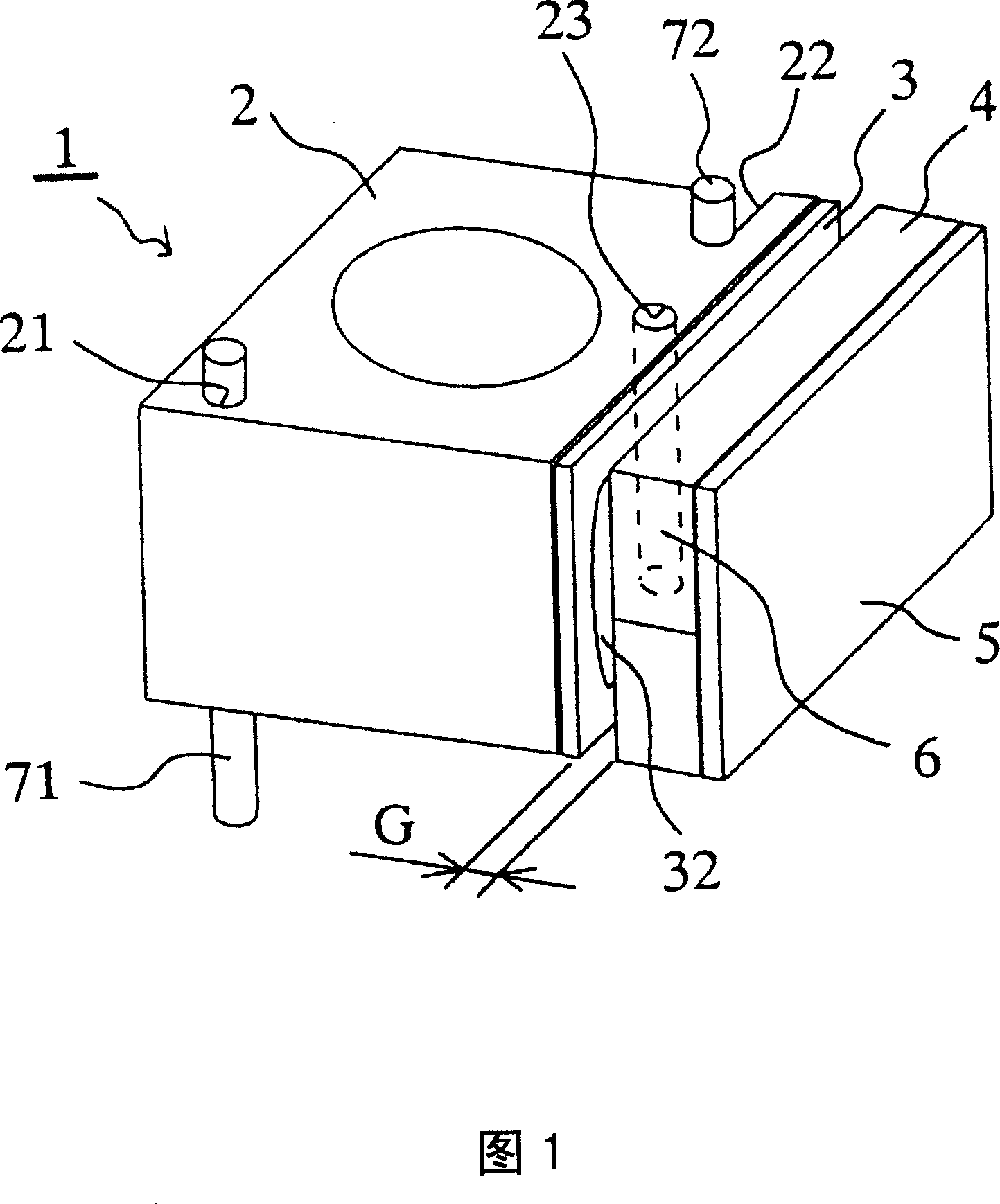
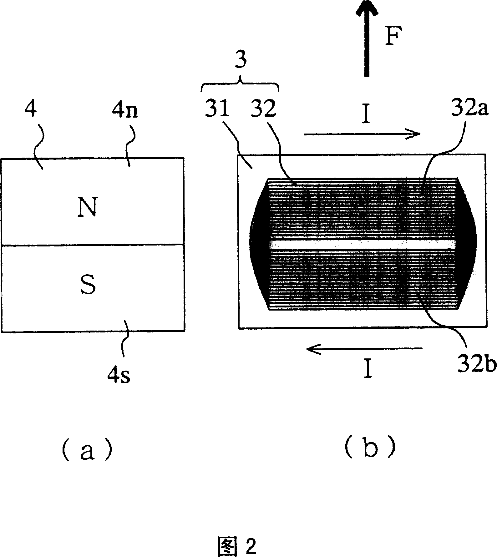
[0027] FIG. 1 shows a lens driving device 1 of a camera device. A lens group (not shown) is provided inside the lens holder 2 . On one side of the lens holder 2, the FP coil 3 is disposed, and the coil pattern 32 is exposed. In addition, a magnet 4 is arranged with a gap G at a position facing the FP coil 3 . The front surface of the magnet 4 faces the FP coil 3 , but the yoke 5 as a magnetic body is attached to the back surface by attraction. The yoke 5 attached to the magnet 4 is fixed to a housing (not shown) of the camera device, although not shown.

[0028] Two shaft-shaped guide mechanisms 71 and 72 are vertically provided as guide mechanisms on a housing (not shown). In addition, the lens holder 2 is provided with a cylindrical through-hole 21 , a notch 22 , and a cylindrical through-hole 23 . The diameter of the through-hole 21 is substantially the same as or slightly larger than the diameter of the first shaft-shaped guide mechanism 71 , and the first shaft-shaped...

Embodiment 2

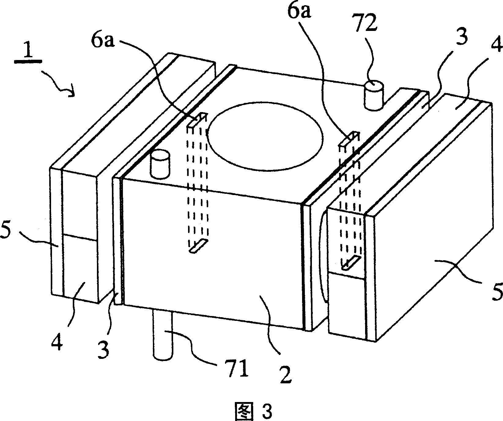
[0033] FIG. 3 shows a perspective view of Example 2. FIG. In addition, in Embodiment 2 and below, the same components and portions as in Embodiment 1 are assigned the same reference signs as in Embodiment 1, and description thereof will be omitted.

[0034] FP coils 3 are respectively arranged on two side surfaces parallel to each other of the lens holder 2 , and magnets 4 with yokes 5 as magnetic bodies attached to the back are arranged at intervals from the respective FP coils 3 . In addition, in the vicinity of the FP coil 3 of the lens holder 2, two magnetic members 6a in the shape of square columns are arranged and fixed with an adhesive (not shown) or the like.

[0035] In Example 2, since two sets of magnetic member 6a, FP coil 3, magnet 4, and yoke 5 are arranged, lens holder 2 can be held more precisely than in Example 1. In addition, instead of providing two magnetic members 6a, only one magnetic member 6a may be provided.

Embodiment 3

[0037] FIG. 4 shows a perspective view of Example 3. FIG. As can be seen from this figure (a), as the guide mechanism of the lens holder 2, instead of using a shaft-shaped guide mechanism, a through hole or a cutout, the first and second convex guide mechanisms provided on the side of the lens holder are used. 26 and 27 are different from Embodiment 1 in that Figure (b) is a plan view of a device in which the lens driving device 1 of Embodiment 3 is incorporated into the frame 8 of the camera device viewed from the moving direction of the lens holder 2 . The cross section of the first convex guiding mechanism 26 is triangular, and the cross section of the second convex guiding mechanism 27 is quadrangular. In addition, at positions corresponding to the convex guides 26 and 27 of the housing 8, a first concave guide 81 having a triangular cross section and a second concave guide 82 having a square cross section are formed.

[0038] The lens holder 2 moves along the optical axi...


PUM


Abstract

The object of the present invention is to provide a lens driving unit which can achieve downsizing, improved resistance to impact, stabilized lens attitude, and reduced power consumption when an auto-focus function is performed. The lens driving unit includes a lens holder accommodating a lens or a group of lenses; a coil disposed on a surface of the lens holder; a magnet disposed at a position spaced from the coil by a predetermined distance; and a magnet yoke installed on the back face of the said magnet. The lens driving unit is characted in that the lens driving unit can move along the optical axis by a guide member, and one or more magnetic member is disposed at the lens holder to fix a position of the lens holder.

Description

technical field [0001] The present invention relates to a lens driving device included in imaging devices such as digital cameras, mobile phones with cameras, and video cameras. Background technique [0002] In an imaging device with autofocus function and zoom function, it is equipped with an optical system composed of a plurality of lenses. The body moves along the optical axis. [0003] As the lens driving device, there are piezoelectric actuators that apply an electric field to deform the crystal and use the displacement, and electromagnetic actuators that use voice coils, in addition to devices using stepping motors. [0004] For example, Patent Document 1 discloses a lens drive device that drives a lens by rotating a lead screw with a stepping motor. In addition, Patent Document 2 discloses an autofocus driver for a camera in which a piezoelectric element is formed in a helical structure to expand displacement. In addition, Patent Document 3 discloses a lens driving...

Claims


Application Information

Patent Timeline
Patent Type & Authority Applications(China)
IPC IPC(8): G02B7/02H04N5/225
CPCG02B7/023
Inventor 山下博司
Owner SANYO ELECTRIC CO LTD
Why Eureka
Try Eureka