Method for shaping bar array large power semiconductor laser device added with guide light

A semiconductor and laser technology, applied in the field of LD, to achieve the effect of compact and reasonable optical path design, precise control, and ensure the stability of the optical path

Inactive Publication Date: 2007-06-06
INST OF OPTICS & ELECTRONICS - CHINESE ACAD OF SCI
View PDF1 Cites 21 Cited by
  • Summary
  • Abstract
  • Description
  • Claims
  • Application Information

AI Technical Summary

Problems solved by technology

However, no guide light is introduced into this optical path

Method used


Image

  • Method for shaping bar array large power semiconductor laser device added with guide light
  • Method for shaping bar array large power semiconductor laser device added with guide light
  • Method for shaping bar array large power semiconductor laser device added with guide light

Examples


Embodiment 1

[0038] Example 1, using a domestic 40W continuous wave LD with a wavelength of 808nm and a 10mW light source with a wavelength of 650nm, through the above optical path for design, processing and assembly, coupled to an optical fiber with a core diameter of 400 μm and a numerical aperture of 0.37, the final output power is LD output power of 28.2 watts , the guided light output is 5.2 milliwatts, and the specific process is as follows:

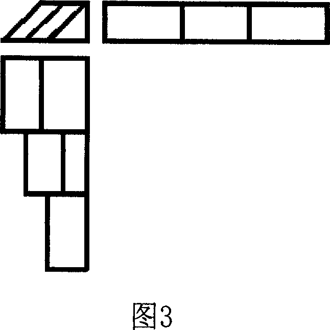
[0039] (1) For an optical fiber with a core diameter of 400 μm and a numerical aperture of 0.37, it is calculated by formula (2) that the principle of optical parameter product matching can be satisfied by folding the LD beam three times. Therefore, it is necessary to make a 3-fold reflective device in this system.

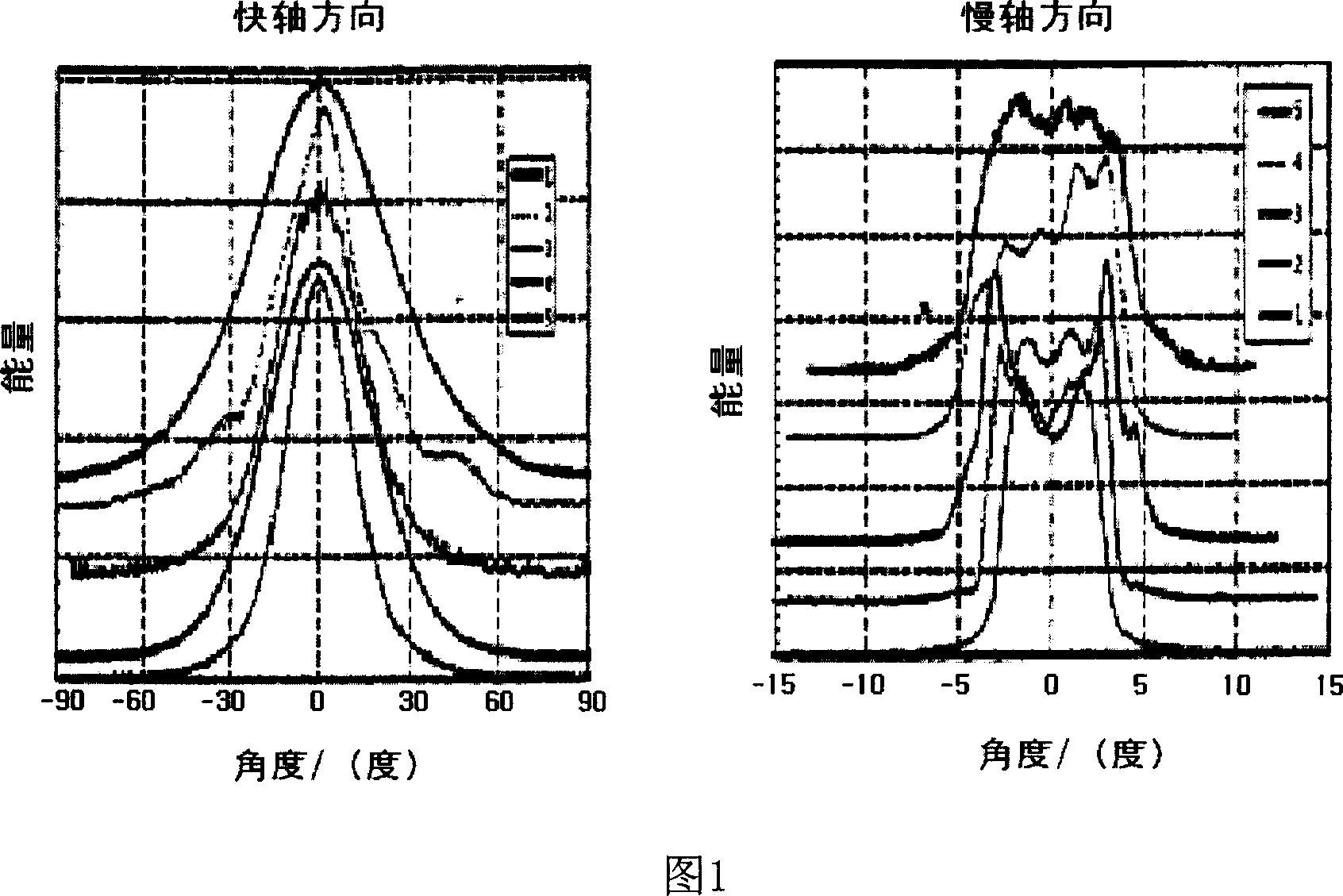
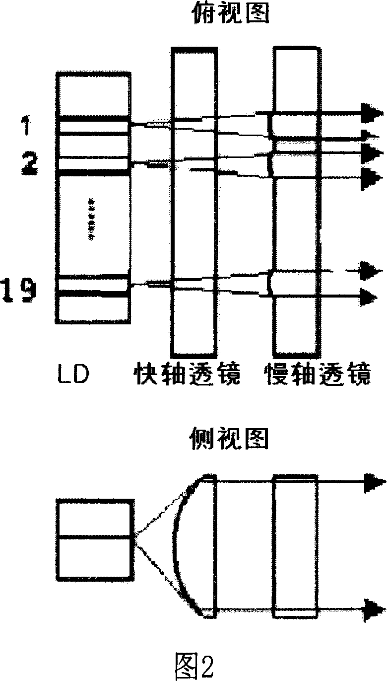
[0040] (2) Realize the alignment of LD(λ 1 =808nm) collimation, the collimated light beam becomes a quasi-parallel light beam. After testing, the divergence angle in the fast axis direction is 10.2mrad, the spot length is 0.6mm, ...


PUM


Abstract

Adding guided light strip array high-power semiconductor laser device (High-Power Laser Diode Bar , LD for short) reshaping method: (1) by calculating the product of the optical fiber core radius and half of the angular aperture, and the optical parameter product of the LD light beam in the direction of quick, slow axis, ascertain the number of times which the LD light beam needed to reshaping, to make reshaping implement with high reflecting efficiency; (2) adopting the quick, slow axis collimation lens array to collimates in two direction of the quick, slow axis alignment of LD, getting the strip collimation facula; (3) assembling reshaping implement , realizes reshaping of the light beam; (4) assembling the focusing lens and optical fiber, adjusting the optical fiber to the right location , making the outputting power of LD maximal;(5)entrancing the guided light in proper location of the reshaping implement, adjusting the guided light to appropriate location, makes the luminous power of the guided light which is output from the optical fiber maximum. The light path design is reasonable and compact, has not changed the light path of LD, has avoided leading into new scattering and reflecting loss, guarantee light path stability of LD.

Description

technical field [0001] The invention relates to a beam shaping method of a high-power semiconductor laser (High-Power Laser Diode Bar, LD for short), in particular to a shaping method of an LD with guiding light added. Background technique [0002] The optical parameter product is an important parameter of the beam. According to the ISO standard, the optical parameter product (Q) is defined as the product of the beam waist radius and half of the far-field divergence angle: [0003] Q=ω 0 θ 0 / 2 = const. (1) [0004] According to ISO regulations, the standard unit of optical parameter product is mm mrad. [0005] According to Siegman's theory, when a beam with a certain beam waist and divergence angle is transformed by an ideal optical element (such as a lens and a mirror) that is passive, not truncated, and has no aberrations, the optical parameter product Q before and after transformation will remain unchanged. This theory is also applicable in LD beam transformation s...

Claims


Application Information

Patent Timeline
Patent Type & Authority Applications(China)
IPC IPC(8): G02B27/14G02B27/00G02B6/32G02B6/26
Inventor 谢伟民周崇喜杜春雷杨欢潘丽战盛龙
Owner INST OF OPTICS & ELECTRONICS - CHINESE ACAD OF SCI
Why Eureka
Try Eureka