Efficient high-speed vapour-liquid mass transfer structure form

A high-speed, vapor-liquid technology, applied in fractionation and other directions, can solve the problems of lower tray efficiency, lower operating capacity upper limit, large tray pressure drop, etc., achieve uniform distribution of vapor and liquid, reduce mist entrainment, mist entrainment small amount of effect

Active Publication Date: 2007-06-13
BC P INC CHINA NAT PETROLEUM CORP +1
View PDF3 Cites 5 Cited by
  • Summary
  • Abstract
  • Description
  • Claims
  • Application Information

AI Technical Summary

Problems solved by technology

The development of the existing jet-lifting trays is mainly reflected in the improvement of the spray element cover. The reason for the decrease in the efficiency of the tray in the case of a large throughput has not been analyzed. In fact, it has been found through experimental research that the reason for the decrease in the efficiency of the tray is Due to the reduction of the relative lift of the liquid during high gas velocity operation, the existing jet trays basically absorb liquid from the tray through the bottom gap of the mass transfer element, and a sufficient negative pressure must be formed to ensure the flow of the liquid. Lifting amount, which requires a sufficiently high steam velocity, at the cost of sacrificing the pressure drop of the tray, and the steam velocity has little effect on the lifting amount after a certain level
[0010] (2) The mixing of the mass-transferred liquid and the non-mass-transferred (not lifted) liquid is another main reason for the low efficiency of the plate
Moreover, there is a problem of liquid circulation in the initial stage of the liquid in the riser jet, which will also restrict the improvement of the liquid lift.
Although some proprietary technologies add another layer of trays above the mass transfer trays to collect the liquid after mass transfer, which can solve the problem of liquid back-mixing, but it will greatly increase the pressure drop of the trays and complicate the structure, resulting in unnecessary energy loss
[0011] (3) Another common disadvantage of the existing spray trays is the large pressure drop of the trays, because the inherent feature of this type of trays is to use the high steam velocity to form a negative pressure at the inlet of the mass transfer element to attract the liquid to rise, and in the A cover or filler should be added to the top of the mass transfer element. The limitation of this infusion method will increase the resistance coefficient of the fluid passing through the tray, reduce the upper limit of the operating capacity, and also restrict the scope of use of this type of tray.
[0012] (4) The existing tray structure is complicated, the cost is high, and maintenance is difficult, so it cannot be applied to coking-prone systems and decompression operations

Method used


Image

  • Efficient high-speed vapour-liquid mass transfer structure form

Examples


Embodiment Construction

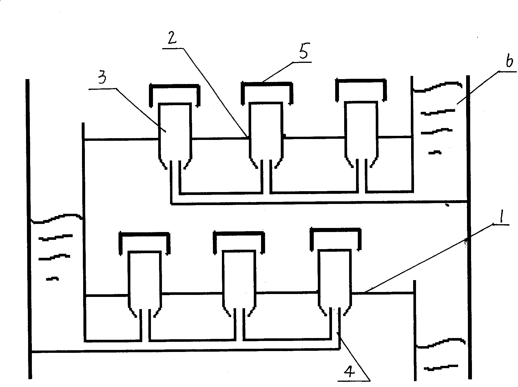
[0032] A high-efficiency and high-speed vapor-liquid mass transfer configuration involved in the present invention is generally installed in a tray tower as shown in the accompanying drawings, and mainly includes a tray 1, a plate hole 2, an air lifter 3, a distribution pipe 4, a top cover 5, a drop The liquid pipe 6, the lifter 3 is installed on the tray 1 through the plate hole 2, the distribution pipe 4 is correspondingly arranged at the lower part of the lifter 3, the top cover 5 is arranged on the top of the lifter 3, the tray 1 and the downcomer 6 Connection, multiple mass transfer elements are connected in parallel on the tray 1, the mass transfer elements are composed of plate holes 2, air lifter 3, distribution pipe 4, top cover 5, the upper part of the air lifter 3 is straight cylindrical, the lower part is a cone bottom, the cone The bottom is below the straight cylinder, the cone bottom has an opening, and a liquid swirl component is installed under the cone bottom....


PUM


Abstract

The present invention relates to a high-effective high-speed vapor-liquid mass transfer structure. It includes the following several portions: column tray, tray hole, vapor riser, distribution pipe, top cover, downflow spout and mass transfer element. Said invention also provides the concrete structure of the above-mentioned every portion and connection mode of all the above-mentioned portions. Said structure can eliminate scale effect of column equipment, and can enhance mass transfer process.

Description

technical field [0001] The invention relates to a high-efficiency and high-speed vapor-liquid mass transfer configuration used in plate towers in petroleum and chemical processing industries. Background technique [0002] Tray tower is the most common vapor and liquid mass transfer equipment. The tray types are generally bubble-cap trays, valve trays and sieve trays. With the development of column technology, separation equipment The requirements are getting higher and higher, and many new trays and internals have been developed to meet the growing needs. [0003] The improvement of the internals of the tray tower basically revolves around the improvement of the vapor-liquid contact configuration on the tray, the way of blowing, the rational use of the tray space, and the reduction of mechanical resistance, so as to reduce the mist entrainment, leakage, etc., and improve the efficiency of the tray. Processing capacity; or reduce back mixing, improve tray efficiency; improve...

Claims


Application Information

Patent Timeline
Patent Type & Authority Applications(China)
IPC IPC(8): B01D3/18
Inventor 刘艳升曹睿刘拥军
Owner BC P INC CHINA NAT PETROLEUM CORP
Why Eureka
Try Eureka