
Temperature difference generator welding method

A technology of thermoelectric generator and welding method, which is applied in the direction of welding equipment, circuits, semiconductor devices, etc. It can solve the problems affecting the thermoelectric conversion efficiency, life of the generator, large single contact resistance, poor joint strength, etc., and achieve high reliability , Low welding contact resistance, good welding strength

Inactive Publication Date: 2007-06-13
CHINA ELECTRONIC TECH GRP CORP NO 18 RES INST
View PDF0 Cites 3 Cited by
  • Summary
  • Abstract
  • Description
  • Claims
  • Application Information

AI Technical Summary

Problems solved by technology

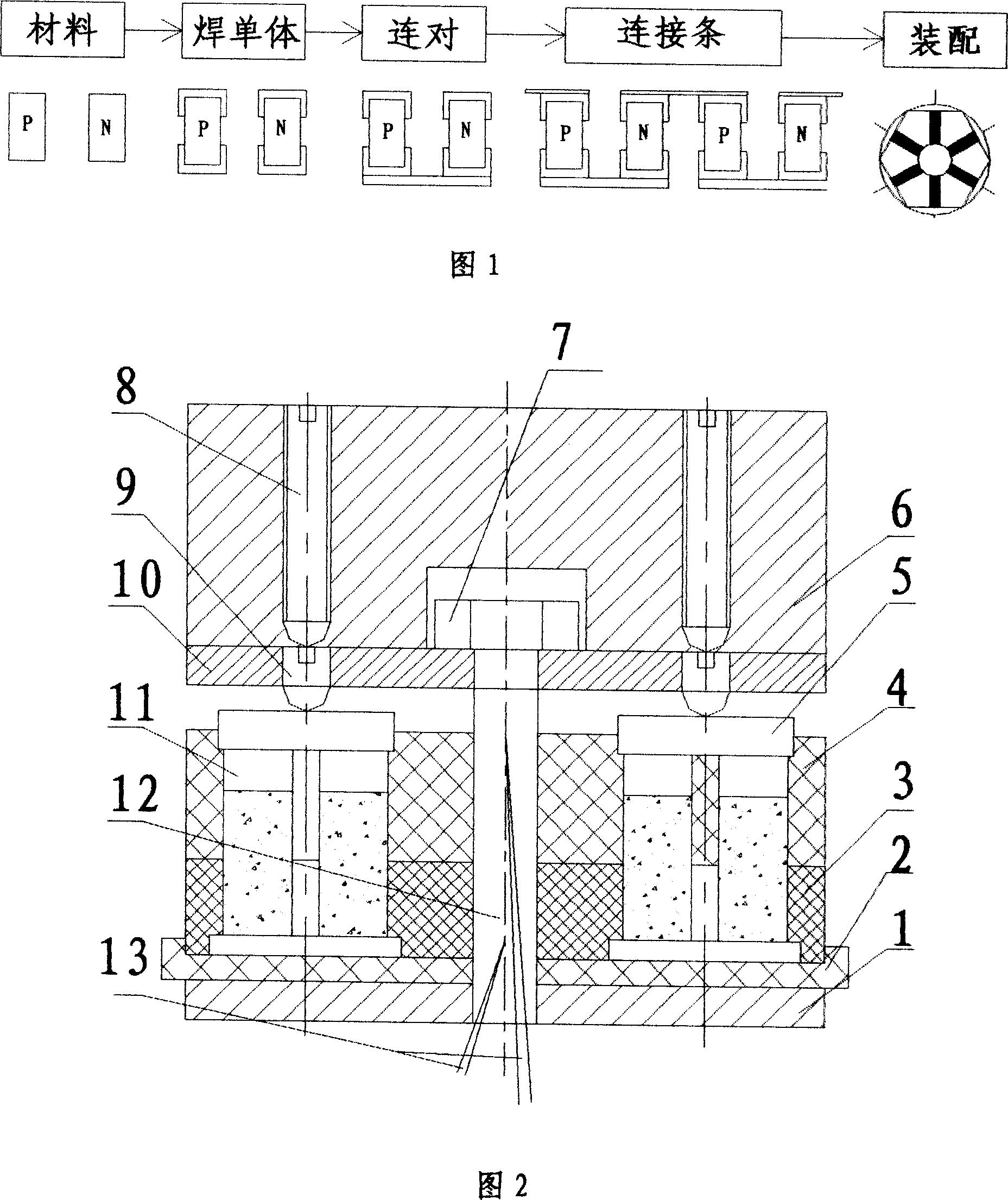
[0003] The currently known thermoelectric welding method is to use SnTe as the solder to weld the flat pure iron electrode and the P and N-type thermoelectric materials to form a single unit, and then use AgCu as the solder to connect the two thermoelectric units into a single unit. The pair of π constitutes the most basic thermoelectric generator; in this process, the two thermoelectric materials are subjected to two high-temperature shocks. Due to the requirements of different P and N-type thermoelectric materials for welding materials, welding temperature requirements and high temperature resistance Different requirements for the number of impacts lead to large contact resistance and poor joint strength after welding. The welding quality of the single material directly affects the thermoelectric conversion efficiency, life, and impact resistance of the generator.

Method used


Image

  • Temperature difference generator welding method
  • Temperature difference generator welding method

Examples


Embodiment 1

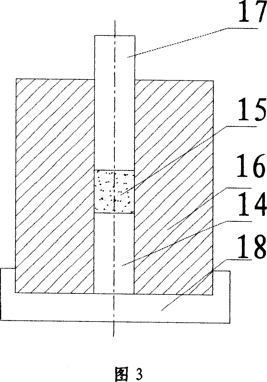
[0013] Embodiment 1: Referring to accompanying drawings 1-3, as shown in Figure 1, the welding method flow chart is to first press out the material as shown in Figure 3: that is, first put the mold lower pressure head 14 into the mold 16, and the mold 16 is placed on the mold bottom support 18, then pour the weighed solder powder 15 into the mold 16, vibrate slightly, then install the mold upper pressure head 17, turn clockwise for 2 to 3 circles, put it on the hydraulic press, and apply pressure. Hold the pressure for 1 minute, demoulding and forming; the method of welding the single body is to put the pressed N-type material into the lower electrode on the thermoelectric generator welding device described in Figure 2, and then put the central tube 12 and the positioning plate 10 and The briquette 6 is put into the furnace for one welding, and then taken out after welding; the connecting method is: put the diversion copper sheet into the lower mold cavity 3, cover the tray 2 a...


PUM


Abstract

The present invention belongs to a welding method of thermo-generator. Said welding method includes the following steps: using mould to respectively make N-type material and P-type material into circular cylinder, placing lower electrode, N-type material and upper electrode into one hole of mould cavity body, placing them into a furnace to make welding, after they are taken out, making secondary welding on said N-type material, placing copper inducer into lower mould cavity, covering tray and baseplate, adding silver-copper filler metal, placing N-type monomer on which the electrode is welded into left mould hole of mould cavity, successively placing lower electrode, P-type material and upper electrode into right mould hole, covering mould cavity, covering positioning plate, making screw be aligned with centre of welding piece, fixing them by using nut, regulating screw on the positioning plate, placing the thermo-generator welding device into furnace, then making N-type material and P-type material be welded together.

Description

technical field [0001] The invention belongs to the technical field of thermoelectric generator manufacturing, and in particular relates to a thermoelectric generator welding method. Background technique [0002] The thermoelectric generator consists of two different metals to form a closed loop. When there is a temperature difference between the two joints, a current will be generated in the loop. This effect constitutes a thermoelectric generator. [0003] The currently known thermoelectric welding method is to use SnTe as the solder to weld the flat pure iron electrode and the P and N-type thermoelectric materials to form a single unit, and then use AgCu as the solder to connect the two thermoelectric units into a single unit. The pair of π constitutes the most basic thermoelectric generator; in this process, the two thermoelectric materials are subjected to two high-temperature shocks. Due to the requirements of different P and N-type thermoelectric materials for welding...

Claims


Application Information

Patent Timeline
Patent Type & Authority Applications(China)
IPC IPC(8): B23K1/008B23K101/40
Inventor 郑海山陈宏根任保国王泽深张建中魏增
Owner CHINA ELECTRONIC TECH GRP CORP NO 18 RES INST
Learn More