
Process for producing transmission cable

A manufacturing method and transmission cable technology, applied in cable/conductor manufacturing, printed circuit manufacturing, insulated cables, etc., to achieve the effects of eliminating noise, reducing manufacturing costs, and suppressing connection resistance

Inactive Publication Date: 2011-03-16
DEXERIALS CORP
View PDF2 Cites 0 Cited by
  • Summary
  • Abstract
  • Description
  • Claims
  • Application Information

AI Technical Summary

Problems solved by technology

For example, in a transmission cable in which only signal lines are formed, malfunction due to noise or mutual interference of signals becomes a big problem

Method used


Image

  • Process for producing transmission cable
  • Process for producing transmission cable
  • Process for producing transmission cable

Examples


Embodiment Construction

[0021] Hereinafter, the transmission cable to which the present invention is applied and its manufacturing method will be described in detail with reference to the accompanying drawings.

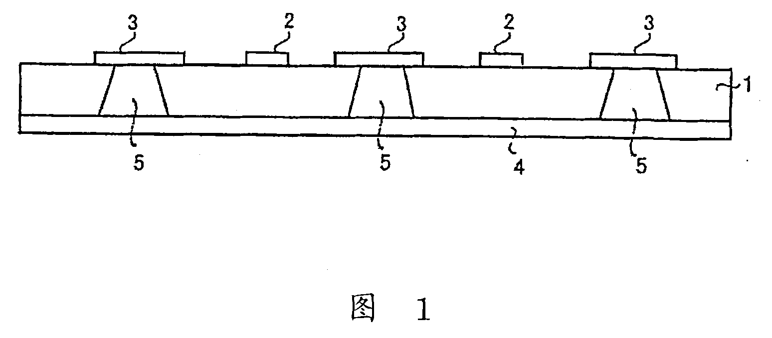
[0022] figure 1 It is a figure showing the structure of the transmission cable to which this invention is applied. In this transmission cable, a signal line 2 is formed on one surface, here, an upper surface, of an insulating layer 1 serving as a substrate, and a ground line 3 is formed thereon. The signal line 2 is used to transmit various signals such as transmission data, and constitutes the center of the transmission cable.

[0023] In this signal line 2, malfunctions due to the entry of noise become a problem, and, as shown in this example, when a plurality of (two) signal lines 2 are formed, the mutual interference between the signal lines 2 become a problem. Therefore, in the transmission cable of this embodiment, the ground wire 3 is provided between these signal wires 2 to elimi...


PUM


Abstract

Disclosed is a transmission cable wherein a plurality of signal lines (2) are formed on one side of an insulating layer (1) and a ground line (3) is formed between the signal lines (2). The ground line (3) is electrically connected with a shield layer (4) formed on the rear surface of the insulating layer (1) through a metal bump (5) embedded in the insulating layer (1). Alternatively, insulatinglayers (1, 6) and shield layers (4, 7) may be formed on the opposite sides of the signal lines (2) and the ground line (3). In this case, the ground line (3) is electrically connected with the shieldlayers (4, 7) respectively through metal bumps (5, 8) on the opposite sides. Consequently, a highly reliable transmission cable capable of high rate transfer and large capacity transfer can be provided.

Description

technical field [0001] The invention relates to a new type of transmission cable with interlayer connections through bumps, and further relates to a manufacturing method of the transmission cable. Background technique [0002] We have developed a flat type transmission cable that can be easily routed to transmit data, etc., through a transmission cable (Internet cable) in various Internets, etc. Flat transmission cables are formed by patterning signal lines using the same method as so-called flexible wiring boards, and have the advantage that there is almost no height difference when wiring in any place such as under floor materials. [0003] However, with the development of the broadband era, high-speed and large-capacity transmission is increasingly required, and it is desired to improve the above-mentioned transmission cables. For example, in a transmission cable in which only signal lines are formed, malfunction due to noise, mutual interference of signals, and the lik...

Claims


Application Information

Patent Timeline
Patent Type & Authority Patents(China)
IPC IPC(8): H01B11/00H01B7/08H01B13/00H05K9/00
CPCH05K3/4647H05K1/0393H05K2201/09236H05K2201/09618H05K1/0219H05K2201/0715H01B11/08H01B7/17H01B13/22
Inventor 小林和好花村贤一郎堀智充
Owner DEXERIALS CORP
Learn More