Energy saving hydraulic lifting system of variable hydraulic counterweight

A hydraulic lifting and variable technology, applied in the direction of fluid pressure actuating system components, elevators, fluid pressure actuating devices, etc. installed power and other problems, to achieve the effect of reducing installed power and energy consumption

Inactive Publication Date: 2007-06-27
ZHEJIANG UNIV
View PDF0 Cites 37 Cited by
  • Summary
  • Abstract
  • Description
  • Claims
  • Application Information

AI Technical Summary

Problems solved by technology

[0004] The energy-saving method of using hydraulic accumulator as hydraulic counterweight can achieve the purpose of recovering excess energy of the system and reducing the installed power of the system when applied in the hydraulic lifting system; but because the output power of the hydraulic accumulator cannot be artificially changed in real time, and if Using a hydraulic accumulator as a hydraulic counterweight also has the disadvantage that the internal oil pressure gradually decreases during the oil output of the accumulator, resulting in a gradual decrease in output power, so that it cannot fully match the power required by the load. Therefore, the installed power of the system is still relatively large; at present, in the lifting system controlled by variable frequency and variable voltage (VVVF), there is still the problem that the excess regenerative energy generated when the lifting platform is heavy-loaded is generally consumed by the braking resistor, so There is a certain waste of energy

Method used


Image

  • Energy saving hydraulic lifting system of variable hydraulic counterweight

Examples


Embodiment Construction

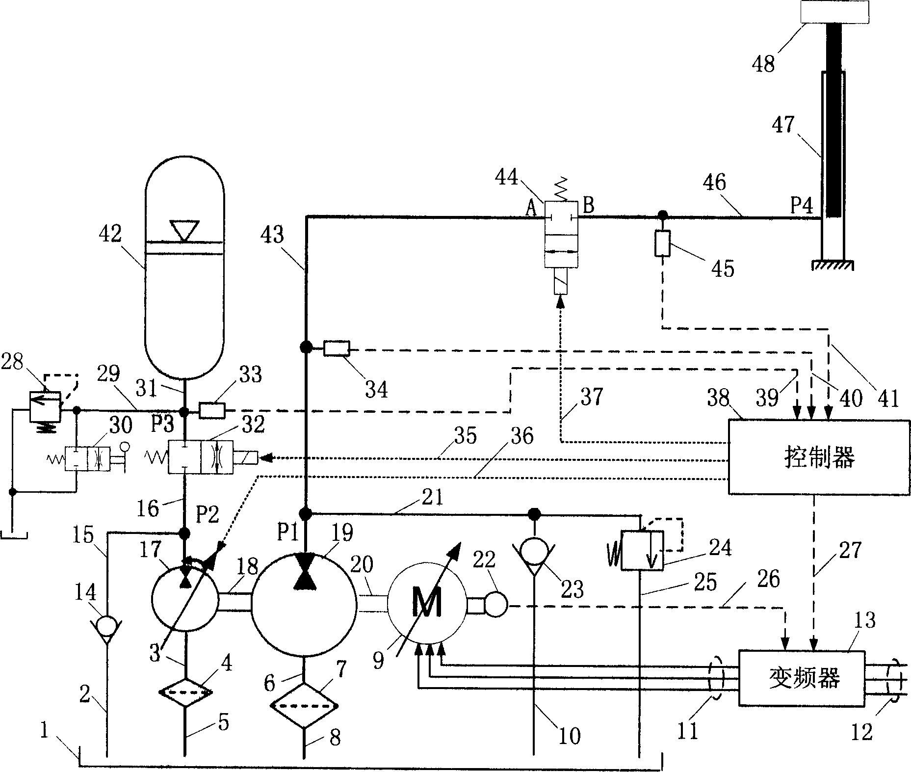
[0032] As shown in the accompanying drawings, the hydraulic system of the present invention is specifically as follows:

[0033] 1) One end of the quantitative pump / motor 19 of the main circuit is connected to the oil tank 1 through the first oil suction line 6 of the quantitative pump / motor, the oil suction filter 7 of the quantitative pump / motor, and the second oil suction line 8 of the quantitative pump / motor, and the other end The oil port P1 is connected to the A port of the two-position two-way solenoid valve 44 of the main circuit through the quantitative pump / motor P1 oil port pipeline 43; the B oil port of the two-position two-way solenoid valve 44 of the main circuit is connected to the hydraulic pressure The cylinder or hydraulic motor 47 is connected; the oil port P1 of the main circuit quantitative pump / motor 19 is connected with the oil tank 1 through the main circuit safety valve pipeline 21, the main circuit safety valve 24, and the main circuit safety valve ret...


PUM


Abstract

An energy-saving hydraulic lift system with variable hydraulic counterweight for the real-time match with load is composed of a primary loop consisting of frequency variator, AC asynchronous motor, quantitative pump / motor, and hydraulic cylinder or hydraulic motor, and a secondary loop consisting of hydraulic energy accumulator (hydraulic counterweight) for recovering the all energy generated by lowering load and variable pump / motor. Said asynchronous motor provides the only energy needed by system efficiency and friction loss.

Description

technical field [0001] The invention relates to a lifting device driven by hydraulic pressure, in particular to an energy-saving hydraulic lifting system with variable hydraulic counterweight. Background technique [0002] The hydraulic lifting system is a device that drives the load up or down by the movement of the hydraulic cylinder or hydraulic motor. It has the advantages of large load capacity, safe and stable operation, and simple structure. Its speed regulation methods include throttling valve control and volumetric speed regulation. Throttle valve-controlled speed regulation uses throttling speed regulation technology to control the operating speed of the system. Its advantages are simple system and convenient control, but there are large throttling and overflow losses in the system, rapid oil temperature rise, and low system efficiency. Disadvantages; while volumetric speed regulation has the advantages of power adaptability, small energy loss and high efficiency....

Claims


Application Information

Patent Timeline
Patent Type & Authority Applications(China)
IPC IPC(8): F15B11/02F15B21/14B66B1/24
Inventor 杨华勇胡东明徐兵黄志勇
Owner ZHEJIANG UNIV
Why Eureka
Try Eureka