Pipe network for connecting metal composite plastic pipe and plastic pipe
A metal composite, plastic pipe fitting technology, applied in the direction of pipe connection arrangement, pipe/pipe joint/pipe fitting, pipe, etc., can solve the problems of unsatisfactory welding, insufficient pressure bearing capacity, unreliable connection, etc., and achieve reliable and convenient connection method. , The effect of increasing reliable performance and reliable pipe network performance
- Summary
- Abstract
- Description
- Claims
- Application Information
AI Technical Summary
Problems solved by technology
Method used
Image

Examples
Embodiment 1
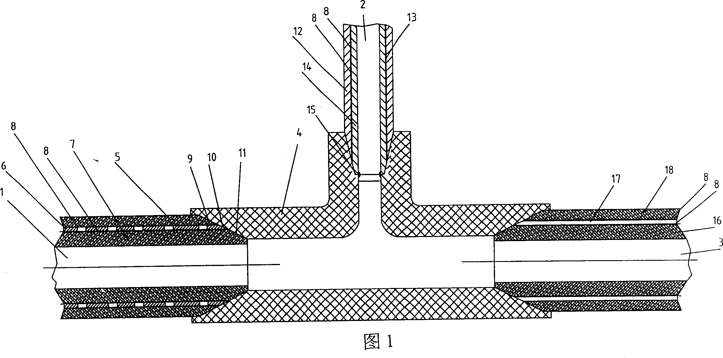
[0029] Fig. 1 has provided the figure of embodiment 1 of the present invention. Referring to Fig. 1, the steel-plastic composite pipe 1, the aluminum-plastic composite pipe 2, and the steel-plastic composite pipe 3 compounded with non-porous steel strips connected by the tee pipe connector 4 form a pipe network. On the plastic outer layer 5 in the steel-plastic pipe 1 compounded with perforated steel strips, there is an inclined conical surface 9 connected to the pipe connector 4, which is molten and connected. The material is non-cross-linked heat-resistant polyethylene (PE-RT). One end of the metal skeleton 6 formed by butt welding of perforated steel strips is also connected to the pipe connector 4 with an oblique cone surface 10, and the inner plastic layer 7 has an oblique cone surface 11 connected to the pipeline connector 4, forming a fusion connection. , the material is also non-crosslinked temperature-resistant polyethylene (PE-RT), and there are adhesives 8 in the ho...
Embodiment 2
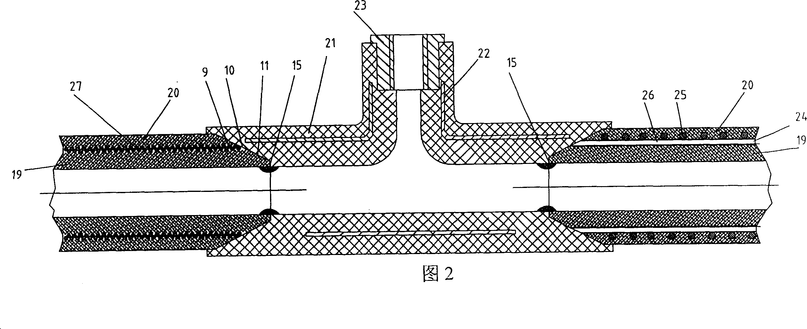
[0036] Fig. 2 has provided the figure of embodiment 2 of the present invention. Embodiment 2 is basically the same as Embodiment 1. The difference is that the inner layer 19 and the outer layer 20 of the composite plastic pipe are all made of PP-R or HDPE, the pipe connector 21 is a tee, and there is a steel plate skeleton 22 in the middle of the pipe connector body. The insert 23, the metal skeleton 24 of the composite pipe at the right end of the pipeline connector is formed by winding the radial steel wire 26 with the latitudinal steel wire 25 and is welded, and the metal skeleton of the composite pipe at the other end is wound with steel wire 27 left and right to form a skeleton. The end faces of the pipes are all thermally fused with the annular step end face 15 of the inner cavity of the pipe fitting.
Embodiment 3
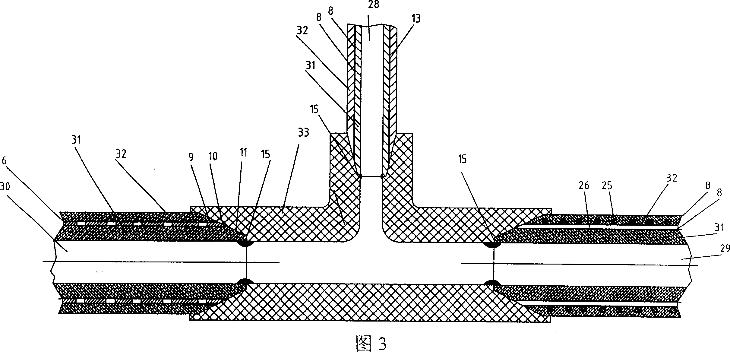
[0038] Fig. 3 has provided the figure of embodiment 3 of the present invention. Embodiment 3 is basically the same as Embodiment 1. The difference is that the inner layer 31 and the outer layer 32 of the composite plastic pipe and the pipe fitting 33 are all silane crosslinked polyethylene materials, and the three metal composite plastic pipes (including silane crosslinked aluminum plastic pipes with butt welding of aluminum strips and adhesive layers) Pipe 28; steel wire welding skeleton silane cross-linked composite pipe 29 with a binder layer in the skeleton, a composite pipe without a binder layer in a perforated steel strip butt welding skeleton 30) the inner layer 31 of the pipe wall and the end face of the plastic pipe are all in contact with the inner chamber The end face 15 of the annular step is in the state of melting connection, the composite pipe 30 with a butt-welded skeleton of a steel strip with holes, and the composite pipe 29 with a steel wire skeleton welded...
PUM
 Abstract
Description
Claims
Application Information
 - R&D
- Intellectual Property
- Life Sciences
- Materials
- Tech Scout
- Unparalleled Data Quality
- Higher Quality Content
- 60% Fewer Hallucinations
Browse by: Latest US Patents, China's latest patents, Technical Efficacy Thesaurus, Application Domain, Technology Topic, Popular Technical Reports.
© 2025 PatSnap. All rights reserved.Legal|Privacy policy|Modern Slavery Act Transparency Statement|Sitemap|About US| Contact US: help@patsnap.com