CT slip-ring system based on optical fibre data-transmission

A technology of data transmission and data acquisition system, applied in the field of computed tomography imaging, can solve the problems of data transmission accuracy and transmission rate limitation, increase the weight and volume of rotating parts, low scanning speed, etc. The effect of low code rate and strong anti-interference ability

Active Publication Date: 2007-07-04
SIEMENS SHANGHAI MEDICAL EQUIP LTD
View PDF0 Cites 38 Cited by
  • Summary
  • Abstract
  • Description
  • Claims
  • Application Information

AI Technical Summary

Problems solved by technology

The disadvantage of the low-pressure slip ring is that the high-voltage generator is set on the rotating part, which rotates with the X-ray tube, which increases the weight and volume of the rotating part, making the scanning speed relatively low
The data transmission method of wireless capacitive coupling overcomes the above-mentioned influence of contact resistance and high-voltage discharge on the transmission signal, but the electromagnetic field of wireless capacitive coupling is relatively easily affected by the interference of external voltage, current and magnetic field changes, so the accuracy of data transmission and transmission rate limited and impacted

Method used


Image

  • CT slip-ring system based on optical fibre data-transmission
  • CT slip-ring system based on optical fibre data-transmission
  • CT slip-ring system based on optical fibre data-transmission

Examples


Embodiment Construction

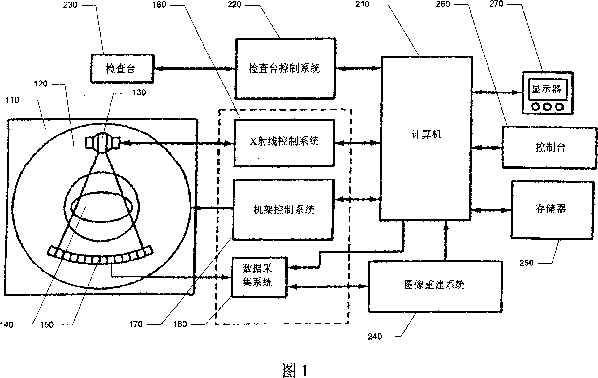
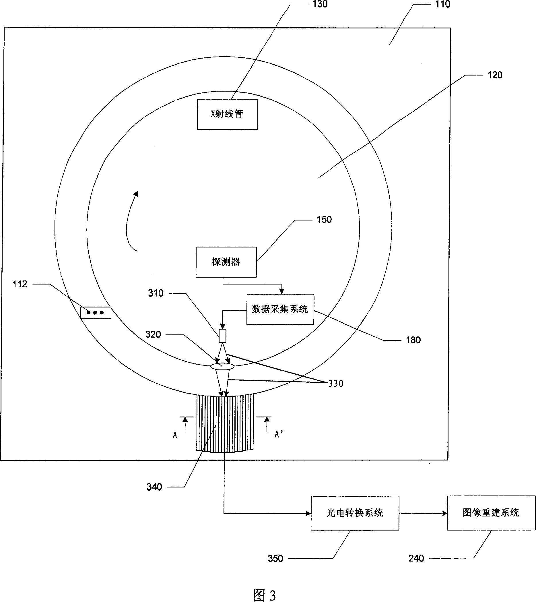
[0022] Referring to FIG. 3 , a CT system is mainly composed of a stationary part 110 , a rotating part 120 , and corresponding control systems and image reconstruction systems. The static part 110 is mainly composed of a frame, a frame control system and a frame main control circuit board; for the sake of simplicity and clarity, only the frame related to the present invention is shown in the figure. The rotating part is mainly composed of X-ray tube and its cooling system and control system, collimator and its control system, filter, detector, data acquisition system, high-voltage generator, etc.; for the sake of simplicity and clarity, only Shown are X-ray tube 130, detector 150 and data acquisition system 180 which are relevant to the present invention.

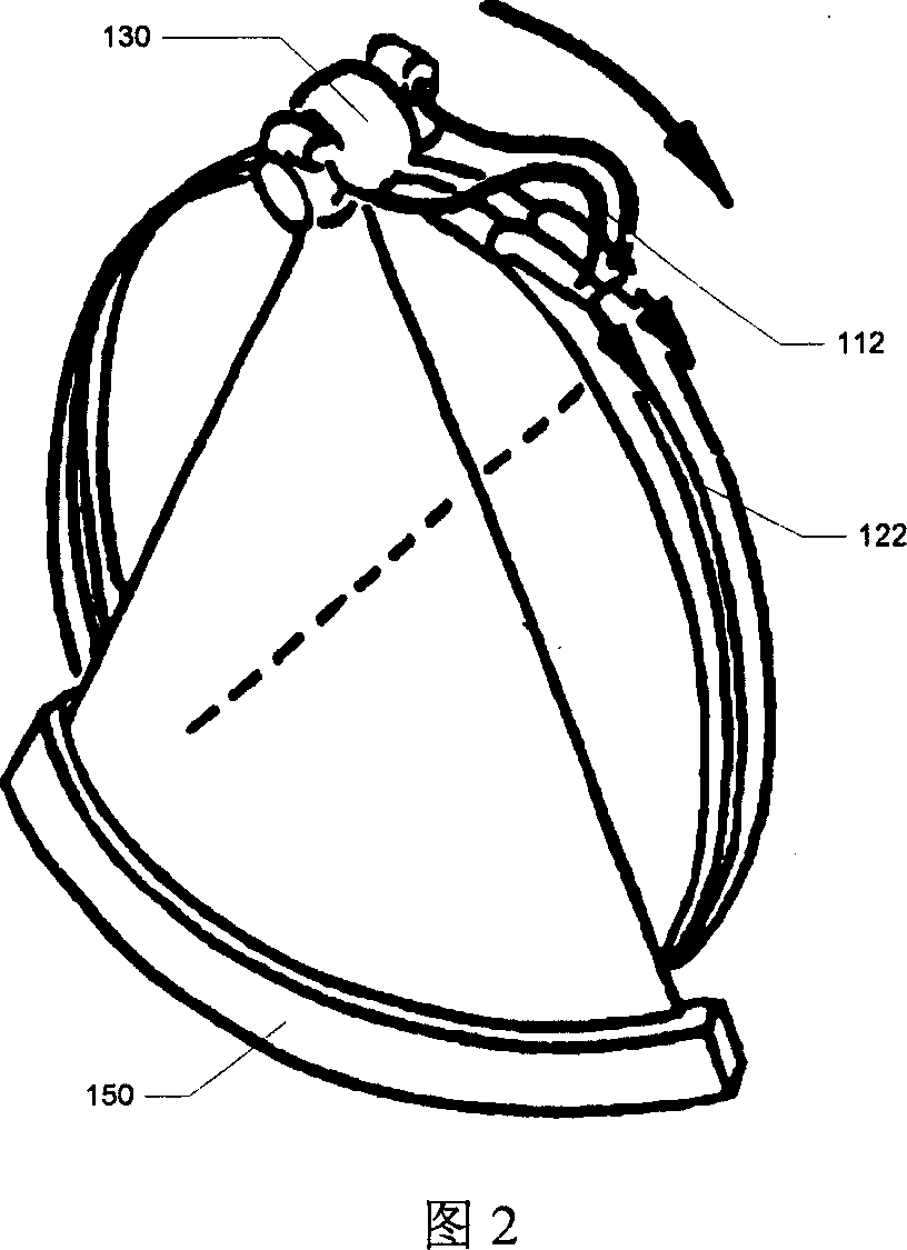
[0023] In the present invention, in order to supply power to the rotating part, an existing method can be adopted, as shown in the figure, the carbon brush 112 is in contact with the slip ring (not shown) for power transmis...


PUM


Abstract

A CT slip-ring system based on optical fibre data transmission applies to the CT system which consists of stationary part and rotating part scanning rotary in said stationary part. It transmits the data from collected from data collect system to external part of rotating part using non-contact optical signals, then transmits the signals to image reconstruction system to reconstructing images after light / electricity conversion. Die to the invention uses the CT slip-ring system based on optical fibre to transmitting data, the interference immunity is strong, it overcomes the problems of data signal reliability decreasing lead by instability of contact resistance when contact-devices transmit data signals and the interference of external electromagnetic field is easier when non-contact wireless capacity coupling transmits data signals and other issues, and meets the requirement of high speed and low error code rate of CT system data transmitting.

Description

technical field [0001] The present invention relates to a data transmission system of a computed tomography (Computed Tomography; "CT" for short) system, in particular to a slip ring system of a CT system. Background technique [0002] A typical CT system is shown in FIG. 1 , which mainly consists of a stationary part 110 , a rotating part 120 , and corresponding control systems and image reconstruction systems. The static part 110 is mainly composed of a rack (Gantry), a rack control system and a rack main control circuit board; for simplicity and clarity, only the rack and rack control system 170 related to the present invention are shown in the figure. The rotating part is mainly composed of X-ray tube (Tube) and its cooling system and control system, collimator and its control system, filter, detector (Detector), data acquisition system (Data Acquisition System; DAS), high voltage generator For simplicity and clarity, only the X-ray tube 130, X-ray control system 160, d...

Claims


Application Information

Patent Timeline
Patent Type & Authority Applications(China)
IPC IPC(8): A61B6/03G01N23/00
Inventor 李永东
Owner SIEMENS SHANGHAI MEDICAL EQUIP LTD
Why Eureka
Try Eureka