Method and device for carrying out a thermodynamic cyclic process

一种热力学循环、压力的技术,应用在蒸汽机装置、机器/发动机、机械设备等方向,能够解决缺少经济性、无有吸引力等问题,达到简化管道铺设的效果

Active Publication Date: 2007-07-04
KALINA POWER LTD
View PDF0 Cites 9 Cited by
  • Summary
  • Abstract
  • Description
  • Claims
  • Application Information

AI Technical Summary

Problems solved by technology

However, its high boiling point makes water unattractive in the first place due to lack of economy when using heat sources with temperatures between 100° and 200° C. such as geothermal liquids or when exothermic by combustion processes

Method used


Image

  • Method and device for carrying out a thermodynamic cyclic process
  • Method and device for carrying out a thermodynamic cyclic process
  • Method and device for carrying out a thermodynamic cyclic process

Examples


Embodiment Construction

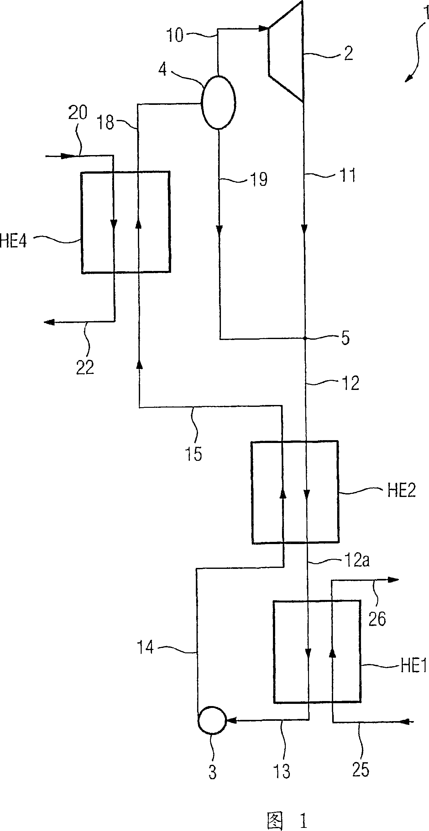
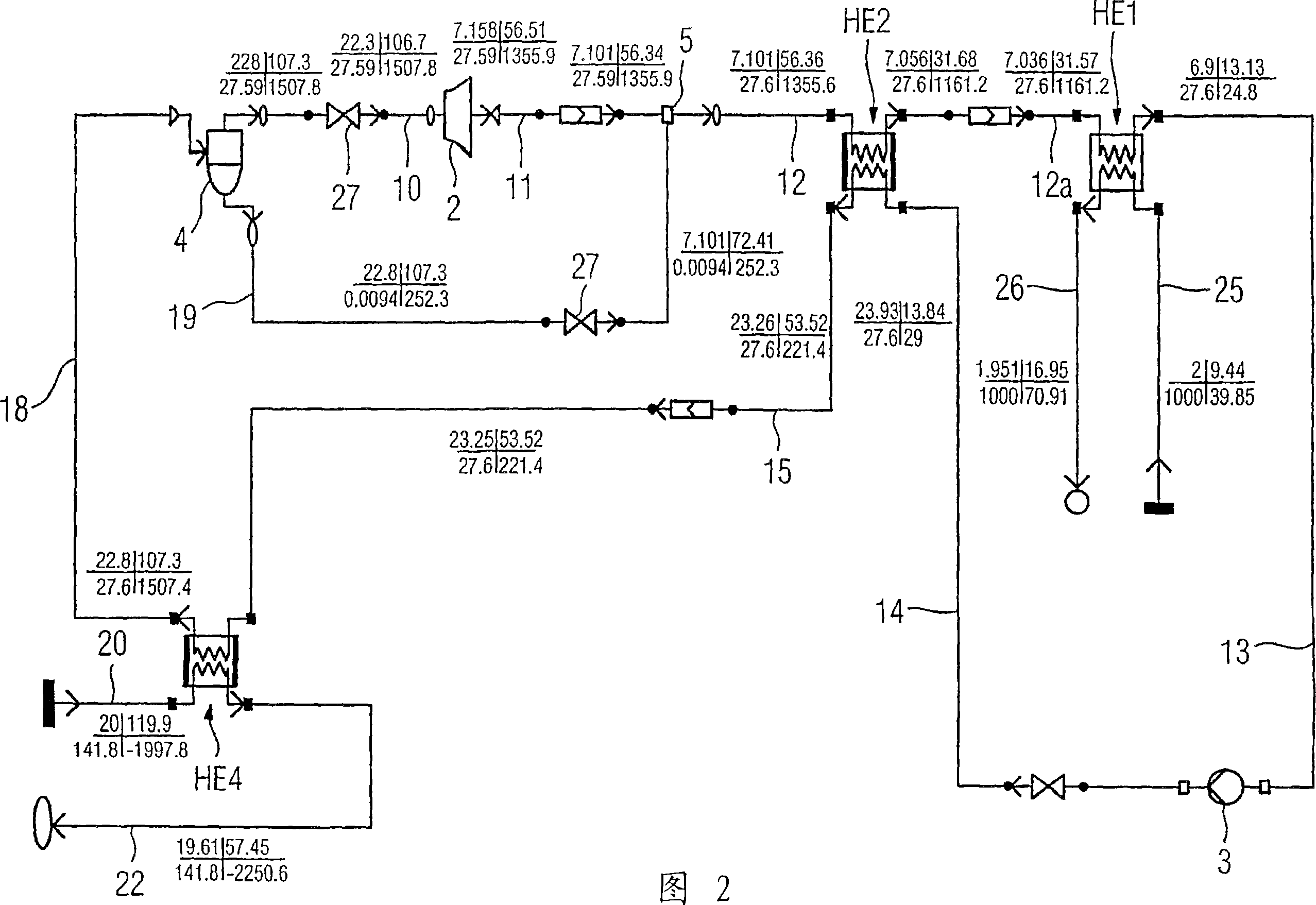
[0022] The device 1 shown in FIG. 1 for carrying out a thermodynamic cycle has a (recovery) heat exchanger HE4 through which on the primary side hot water 20 of a geothermal source not described in detail flows through and on the secondary side It is connected on the one hand to the heat exchanger HE2 and on the other hand to the separator 4 . The separator 4 serves to separate the vapor phase from the liquid phase of a partially vaporized working medium. A steam side outlet of the separator 4 is connected to a turbine 2 . The turbine 2 is connected on the outlet side to a mixer 5 which is also connected to a liquid outlet of the separator 4 . The mixer 5 is connected on the outlet side to the secondary side of a (recovery) heat exchanger HE2 which in turn is connected to the primary side of a condenser HE1 through which cold water flows through the secondary side. At its primary-side outlet, the condenser HE1 is connected via a pump 3 to the primary side of the heat exchang...


PUM


Abstract

The aim of the invention is to reduce the complexity of a cyclic process. To this end, the pressure of a liquid working substance flow (13) is increased and a first partially evaporated working substance flow (15) is produced by the partial condensation of a working substance flow (12) with a low surface tension. Further evaporation of the first partially evaporated working substance flow (15) with heat transmitted by an external heat source (20) produces a second at least partially evaporated working substance flow (18). In said second at least partially evaporated working substance flow (18), the vaporous phase (10) is separated from the liquid phase, the energy of the vaporous phase (10) is converted into a usable form, and a vaporous phase (11) with a low surface tension is combined with the liquid phase (19) in such a way as to form the working substance flow (12) with a low surface tension. The liquid working substance flow (13) is, in turn, obtained by complete condensation of the partially condensed working substance flow (12a) with a low surface tension.

Description

technical field [0001] The invention relates to a method and a device for carrying out a thermodynamic cycle according to claims 1 and 8 . Background technique [0002] A heat engine uses a thermodynamic cycle to convert heat into mechanical or electrical energy. Traditional heat engines generate thermal energy by burning fuel (firstly, fossil energy carriers coal, oil and gas). In this case, the cycle is operated, for example, on the basis of a typical Rankine cycle with water as the working medium. However, its high boiling point makes water unattractive due to lack of economy, both when using heat sources with temperatures between 100° and 200° C., such as geothermal liquids, or when exothermic by combustion processes. [0003] For heat sources with such lower temperatures, the most diverse technologies have been developed in the last few years, which allow their heat to be converted with good efficiency into mechanical or electrical energy. In addition to the Rankine-...

Claims


Application Information

Patent Timeline
Patent Type & Authority Applications(China)
IPC IPC(8): F01K25/06F01K7/00F01K25/08
CPCF01K25/065Y02E10/10
Inventor 乔尔格·伦格特
Owner KALINA POWER LTD
Why Eureka
Try Eureka