Supercharge Your Innovation With Domain-Expert AI Agents!

Optical pickup apparatus and optical information recording and/or reproducing apparatus

一种光拾取装置、记录介质的技术,应用在用光学方法记录/重现、光学记录头、光束引导装置等方向,能够解决增加光学系统制造工艺、光拾取装置大型化成本增大等问题

Inactive Publication Date: 2007-07-04
KONICA MINOLTA OPTO
View PDF1 Cites 2 Cited by
  • Summary
  • Abstract
  • Description
  • Claims
  • Application Information

AI Technical Summary

Problems solved by technology

[0010] According to the technology disclosed in Patent Document 1, since a symmetrical collimator with a positive lens and a negative lens attached thereto is used as an essential structural element, there is a problem of increasing the manufacturing process of the optical system
In addition, in the technique of Patent Document 1, since a photodetector is required for each light source, there is a problem that the size of the optical pickup device increases and the cost increases.

Method used


Image

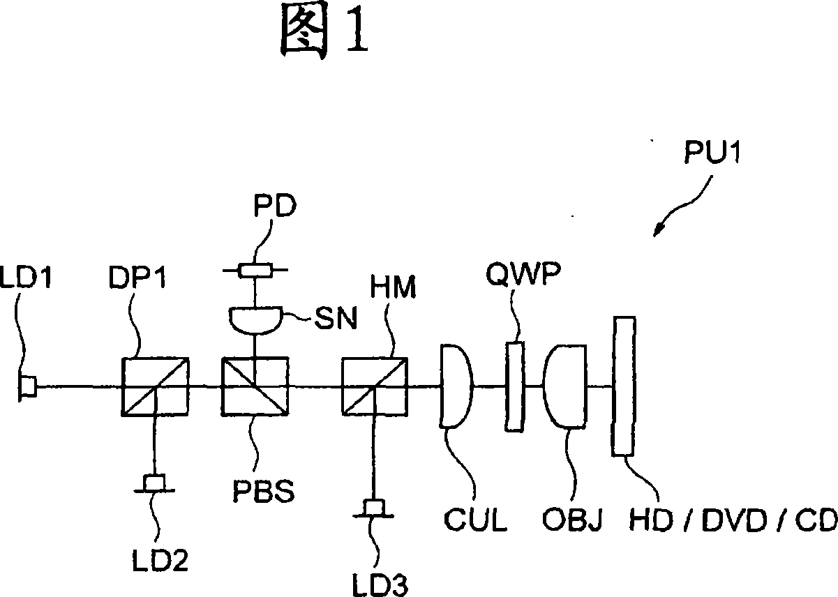
  • Optical pickup apparatus and optical information recording and/or reproducing apparatus
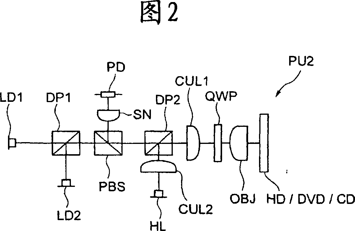
  • Optical pickup apparatus and optical information recording and/or reproducing apparatus
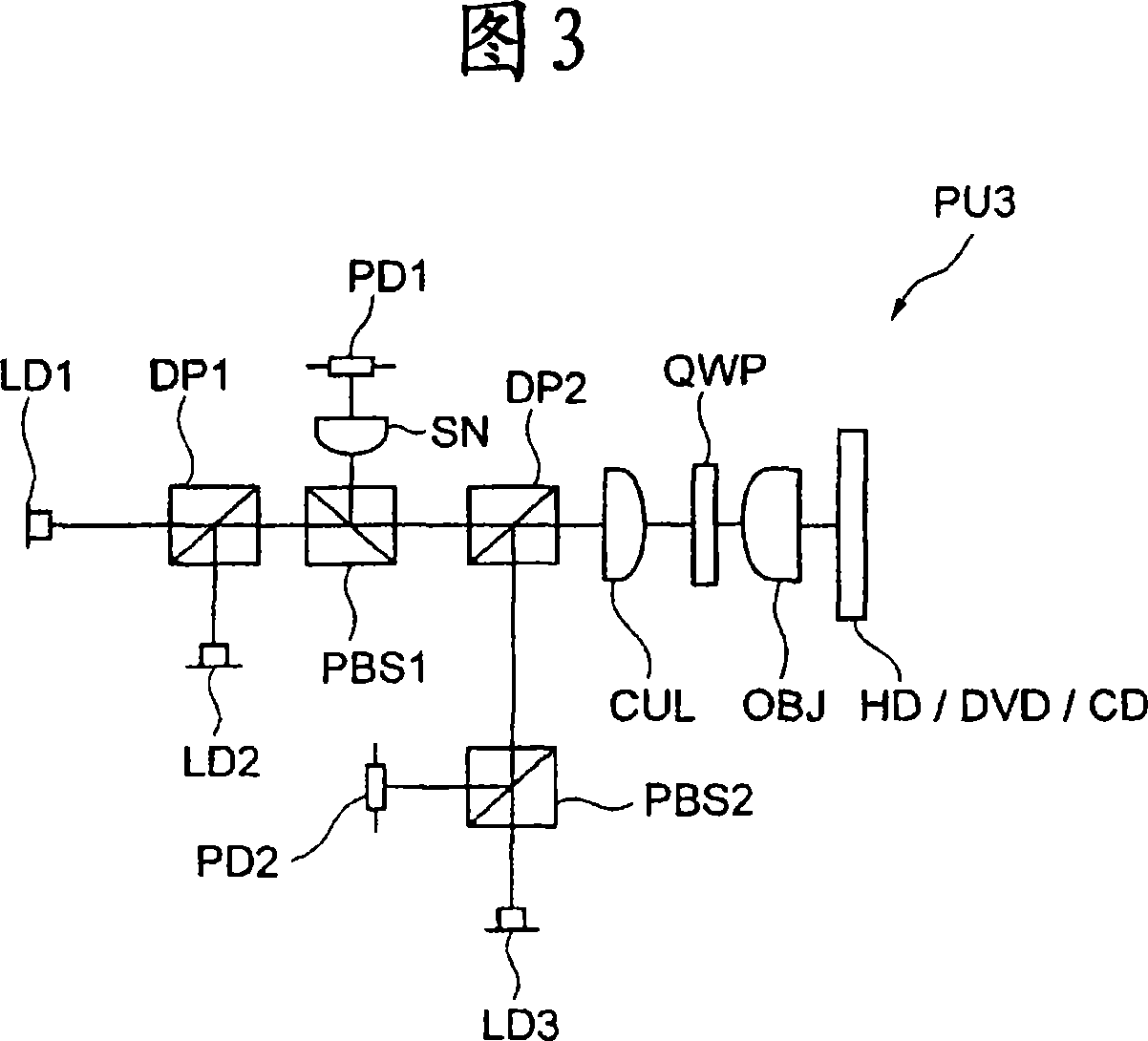
  • Optical pickup apparatus and optical information recording and/or reproducing apparatus

Examples


Embodiment 1

[0257] Table 1 shows the lens data of Example 1. Example 1 uses an objective optical element with a focal length of 3.1 mm for a beam of wavelength λ1, and is designed so that the magnification Mt of the entire optical system is 9 times. The photodetector can use the same device configuration for beams of wavelength λ1 and λ2. In this case, m1 (the magnification of the objective optical element) is 0.09, which can sufficiently allow deterioration of the spherical aberration when the temperature changes. M1 is 0.965.

[0258] [Table 1]

[0259] Example 1 lens data

[0260] (objective lens)

[0261] focal length f 1 =3.1mmf 2 =3.25mm f 3 =3.22mm

[0262] Numerical aperture on the image side NA1: 0.65 NA2: 0.65 NA3: 0.5

[0263] Dihedral Diffraction Number dor: 2 dor: 1 dor: 1

[0264] side i

ri

di (407nm)

ni (407nm)

di (655nm)

ni (655nm)

di (785nm)

ni (785nm)

1

0.250

0.250

0.250

...

Embodiment 2

[0294] Table 2 shows the lens data of Example 2. Example 2 uses an objective optical element with a focal length of 3.1 mm for a beam of wavelength λ1, and is designed such that the overall magnification Mt of the optical system is 8 times. For beams of wavelength λ1 and λ2, the photodetector can use the same device configuration. At this time, m1 (the magnification of the objective lens optical element) is 0.03, which can fully allow the deterioration of the spherical aberration when the temperature changes, and the spherical aberration when the temperature changes Aberration deterioration is 0.051λrms. If the magnification m1 is smaller than 0.01, the deterioration of spherical aberration at the time of temperature change will further increase, and since it is difficult to suppress the deterioration of spherical aberration in the entire optical pickup to 0.07λrms, m1≥0.01 is preferable. M1 = 0.863.

[0295] [Table 2]

[0296] Example 2 lens data

[0297] (objective lens)...

Embodiment 3

[0332]Table 3 shows the lens data of Example 3. Example 3 uses an objective optical element with a focal length of 1.6 mm for a beam of wavelength λ1, and is designed such that the magnification Mt of the entire optical system is 8 times. For light beams of wavelength λ1 and λ2, the photodetector can use the configuration of the same device. At this time, m1 (magnification of the objective lens optical element) is 0.05, and the working distance when recording and reproducing with light of wavelength λ1 is 0.51mm. When the magnification m1 exceeds 0.08, the working distance of the light beam with the wavelength λ1 is shorter than 0.4 mm. Since the optical disc and the objective optical element may interfere with each other, it is preferable that m1≤0.08. M1 = 0.901.

[0333] [table 3]

[0334] Embodiment 3 lens data

[0335] (objective lens)

[0336] focal length f 1 =1.60mm f 2 =1.67mm f 3 =1.66mm

[0337] Numerical aperture on the image side NA1: 0.65 NA2: 0.65 NA3: 0...


PUM

PropertyMeasurementUnit
lengthaaaaaaaaaa
wavelengthaaaaaaaaaa
lengthaaaaaaaaaa

Abstract

An optical pickup in which aberration can be properly corrected through a simple arrangement, and an optical information recorder / reproducer. The optical pickup for recording or reproducing information on a first optical information recording medium including a protective layer having a thickness of t1 and a second optical information recording medium including a protective layer having a thickness of t2 comprises a first light source emitting a first light beam of a wavelength Lambada 1, a second light source emitting a second light beam of a wavelength Lambada 2, an exit angle conversion element that is a single lens for converting the exit angle of the first and second incident light beams, an objective optical element for condensing the first and second light beams to the information recording surfaces of the first and second information recording media, a means for separating the first and second light beams emitted from the first and second light sources and the first and second light beams reflected by the information recording surfaces of the first and second information recording media, and a photodetector receiving the first and second reflected light beams, and is characterized in that the opposite optical surfaces of the exit angle conversion element through which the first and second light beams pass are respectively constituted of a refractive surface.

Description

technical field [0001] The present invention relates to an optical pickup device and a recording / reproducing device for an optical information recording medium. Background technique [0002] In recent years, the research and development of a high-density optical disc system for recording or reproducing information using a blue-violet semiconductor laser with a wavelength of about 400 nm is rapidly progressing. As an example, in the so-called Blu-ray Disc (hereinafter referred to as BD) that records and reproduces information on an optical disc with a specification of NA0.85 and a light source wavelength of 405nm, for DVD (NA0.6, a light source wavelength of 650nm, Storage capacity 4.7GB) A disc with a diameter of 12cm of the same size can record 23 to 27GB of information per layer, or a disc that records and reproduces information at NA0.65 and a light source wavelength of 405nm is the so-called HD DVD (Hereinbelow, referred to as HD), for an optical disc with a diameter of...

Claims


Application Information

Patent Timeline
Patent Type & Authority Applications(China)
IPC IPC(8): G11B7/135G11B7/125
CPCG11B7/13922G11B7/1376G11B2007/0006G11B7/1275G11B7/1378
Inventor 和智美佳池中清乃坂本胜也
Owner KONICA MINOLTA OPTO
Features
  • R&D
  • Intellectual Property
  • Life Sciences
  • Materials
  • Tech Scout
  • Unparalleled Data Quality
  • Higher Quality Content
  • 60% Fewer Hallucinations
Learn More