Thermal interface material and electronic device using same

A technology of thermal interface materials and electronic devices, applied in heat exchange materials, cooling/ventilation/heating transformation, chemical instruments and methods, etc., can solve problems that affect the normal operation of electronic components, cannot be effectively contacted, damaged, etc.

Inactive Publication Date: 2007-07-11
FU ZHUN PRECISION IND SHENZHEN +1
View PDF0 Cites 4 Cited by
  • Summary
  • Abstract
  • Description
  • Claims
  • Application Information

AI Technical Summary

Problems solved by technology

[0002] With the rapid development of the electronic industry, the high speed, high frequency and integration of electronic components make the heat increase sharply. Therefore, it is necessary to install a heat sink on the electronic component to dissipate the heat generated by the electronic component. The contact surface with the electronic components is not completely flat, so the two cannot be effectively contacted when they are bonded together, resulting in poor heat dissipation and directly affecting the normal operation of the electronic components
[0003] The industry usually adds a thermal interface material on the contact surface of the heat sink and the electronic component to fill the gap between the contact surfaces and enhance the heat conduction effect. However, the thermal interface material usually needs to be cut into different shapes or shapes during production and use. It is squeezed, so it is easy to break or damage, so it needs to be improved

Method used


Image

  • Thermal interface material and electronic device using same

Examples


Embodiment Construction

[0010] The present invention is described in detail below in conjunction with embodiment.

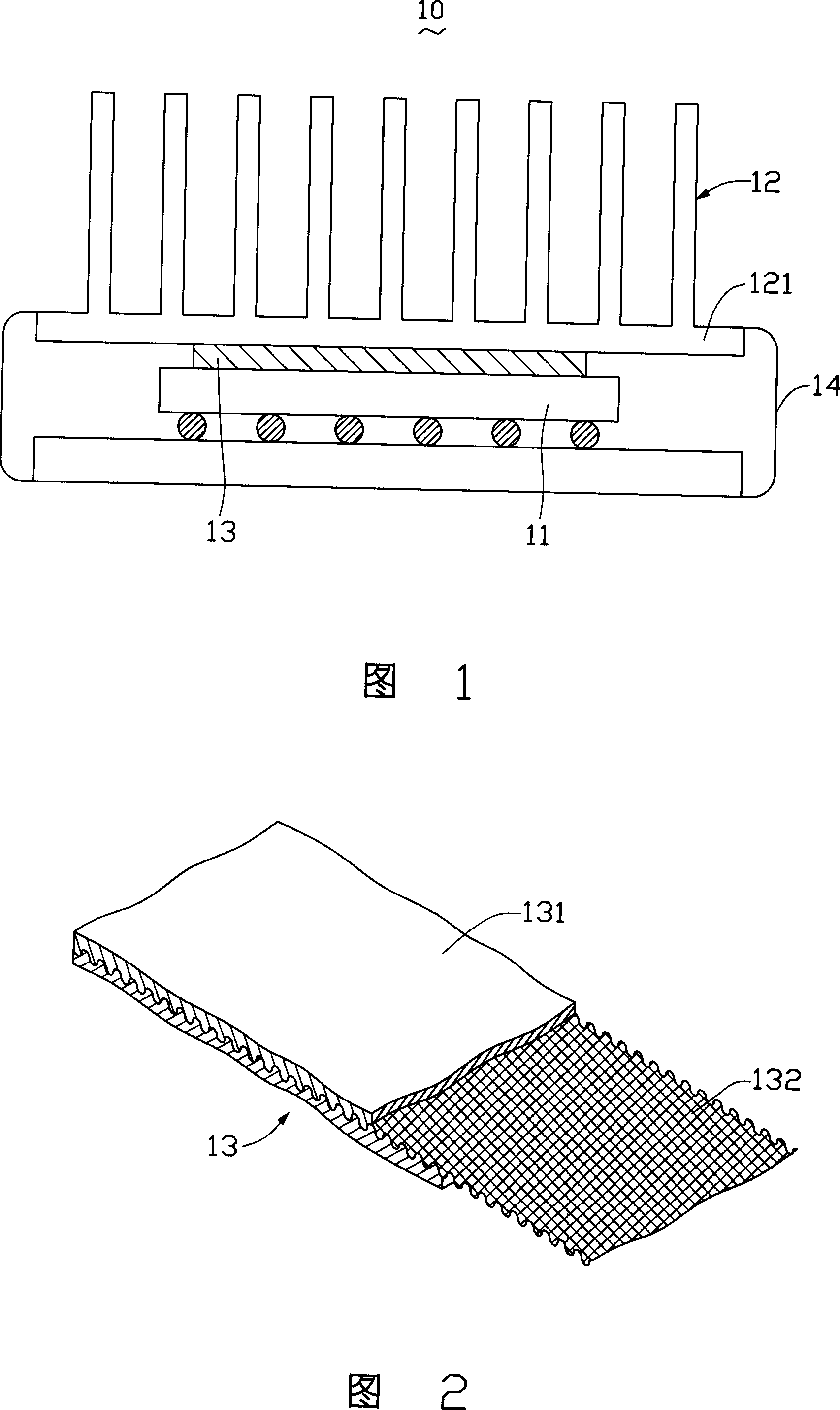
[0011] Please refer to FIG. 1 , the thermal interface material 13 of the present invention, the heat dissipation component 12 and the fastening device 14 form a heat dissipation device 10 to dissipate heat from the heat generating component 11 . The heat dissipation component 12 has a base plate 121, the thermal interface material 13 is attached between the heat generating component 11 and the base plate 121, and the fastening device 14 tightly fastens the heat dissipation component 12 on the heat generating component 11, so that the thermal interface The material 13 is fully filled in the gap between the heating element 11 and the substrate 121 of the heat dissipation element 12 , reducing the contact thermal resistance between the heat generating element 11 and the heat dissipation element 12 , so that the heat dissipation device 10 achieves a good heat dissipation effect.

[0012] Re...


PUM

PropertyMeasurementUnit
thicknessaaaaaaaaaa

Abstract

The invention discloses an electronic device, which comprises the following parts: heating component, radiating component and heat interface material between heating and radiating components, wherein the heat interface material displays piece shape, which contains sulfurizing chip and reinforcing film buried in the sulfurizing chip; the sulfurizing chip consists of indoor-temperature sulfurizing silicon rubber and zinc oxide powder in the silicon rubber; the even grain size of zinc oxide is 0.1-5um; the reinforcing film improves physical strength of heat interface material, which can form different cutting shapes without breaking or damaging due to squeezing.

Description

【Technical field】 [0001] The invention relates to a thermal interface material and an electronic device using the thermal interface material. 【Background technique】 [0002] With the rapid development of the electronic industry, the high-speed, high-frequency and integration of electronic components cause the heat to increase sharply. Therefore, it is necessary to install a heat sink on the electronic component to dissipate the heat generated by the electronic component. The contact surface with the electronic component is not completely flat, so the two cannot be effectively contacted when they are attached, resulting in poor heat dissipation and directly affecting the normal operation of the electronic component. [0003] The industry usually adds a thermal interface material on the contact surface of the heat sink and the electronic component to fill the gap between the contact surfaces and enhance the heat conduction effect. However, the thermal interface material usuall...

Claims


Application Information

Patent Timeline
Patent Type & Authority Applications(China)
IPC IPC(8): C09K5/14H05K7/20
Inventor 郑景太郑年添
Owner FU ZHUN PRECISION IND SHENZHEN
Why Eureka
Try Eureka