Light high-strength composite pipe and production method thereof

A high-strength, composite pipe technology, applied in the direction of slender elements, building elements, etc., can solve the problems of wasting raw materials, increasing the weight of the roller body, and making it difficult for the roller body to rotate normally.

Inactive Publication Date: 2007-07-11
陈联社 +1
View PDF1 Cites 2 Cited by
  • Summary
  • Abstract
  • Description
  • Claims
  • Application Information

AI Technical Summary

Problems solved by technology

[0003] This method is called round inner roller forming method, and its disadvantages are: as the length of the roller body increases, the weight of the roller body increases continuously due to the increase of the diameter, which not only wastes raw materia

Method used


Image

  • Light high-strength composite pipe and production method thereof
  • Light high-strength composite pipe and production method thereof

Examples


Embodiment approach 1

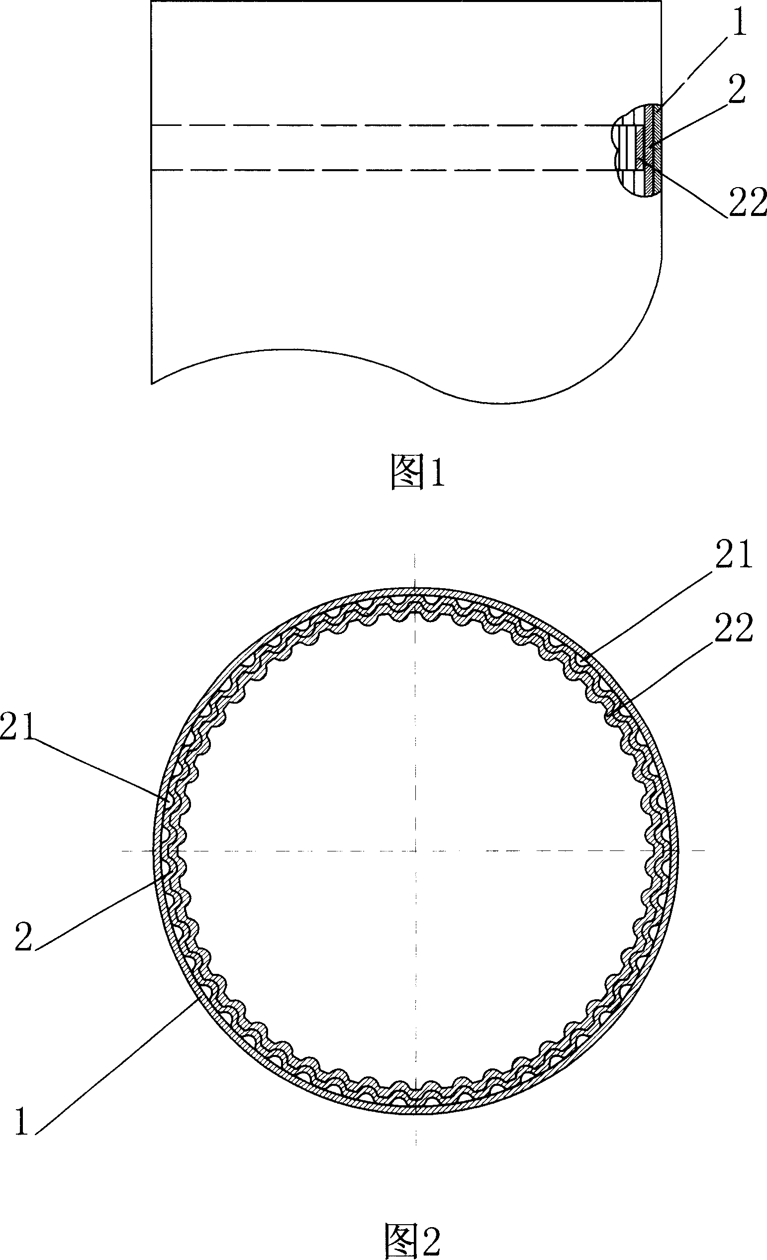
[0017] As shown in Figure 1, Figure 2, Figure 3, and Figure 4, a light-duty high-strength composite pipe is composed of double-layer steel coiled pipes, the outer layer is made of thin stainless steel coiled pipe 1, and the inner layer is made of thin carbon steel plates The coiled tube 2 is formed, and according to the diameter and length of the roll body, the inner thin carbon steel coiled tube is made with several reinforcement tubes in alternate shapes of concavo-convex 21 .

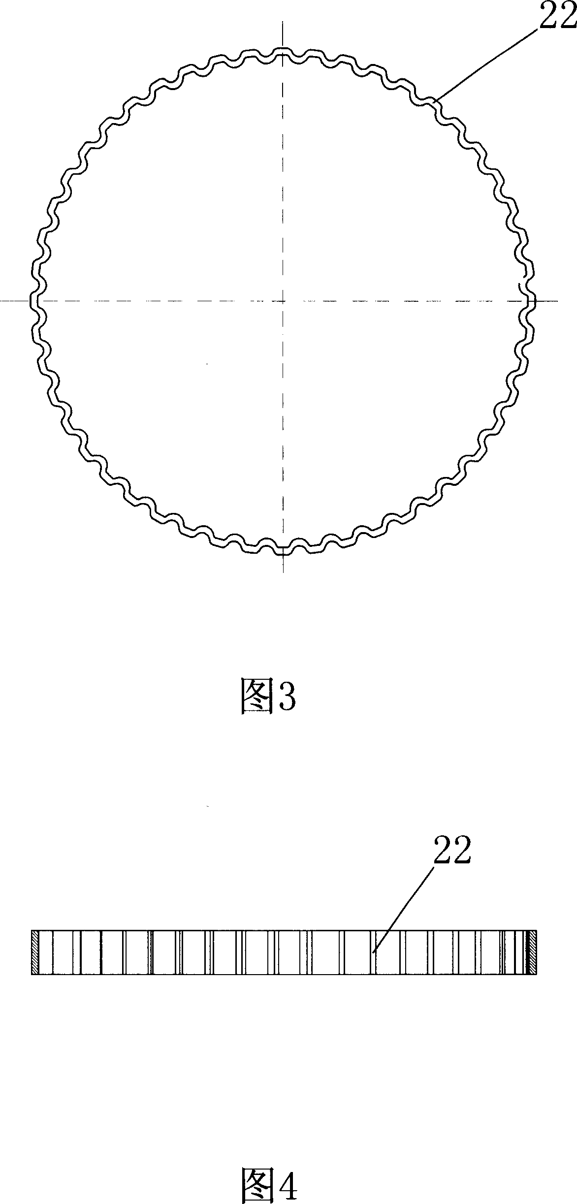
[0018] In order to increase the radial strength and the roundness of the pipe body, several support hoops 22 are added in the thin carbon steel pipe.

[0019] Wherein the cross section of concave-convex groove 21 is semicircular, also can be U-shaped, triangular, trapezoidal etc.

[0020] A manufacturing method of a lightweight high-strength composite pipe is as follows:

[0021] 1. Cut the material according to the size. 2. Use the mold with several alternating concave and convex shapes to make the...

Embodiment approach 2

[0024] Manufacture Ф150×2000mm cloth guide roller tube body, material selection: the outer layer is 1mm stainless steel plate, the inner layer is 1mm carbon plate, the manufacturing method of a light-duty high-strength composite tube is as follows:

[0025] 1. Cut the material according to the size, take 1mm carbon steel plate 2. Use the mold with several concave and convex alternate shapes to make the blanked plate into a plate with several concave and convex alternate shapes, and leave a margin for the next stretching and shaping 3. Trim the edge according to the unfolded size 4. Roll it into a cylinder with a mold, 5. Spot weld and weld the clamping roller body 6. Make the inner roller decently under the action of tension, and use a concave-convex mold for shaping 7. Under the action of tension, the roller body is cold-extruded with a mold to meet the required size requirements for compounding with the outer roller body to form the inner roller body. 8. Fix the outer roller ...


PUM


Abstract

The invention relates to a light high-strength composite pipe and the manufacturing method. The pipe is compounded by double-layer steel reel pipe. The outer layer is made of thin stainless steel reel pipe and the inner layer is made of thin carbon steel reel pipe. Reinforced rib tube with several concave-convex alternation shapes. The manufacturing method is that 1, cutting by the dimension; 2, fabricating the cut plate into the plate with several concave-convex alternation shapes by the mould with several concave-convex alternation shapes and retaining the margin for next drawing and shaping procedure; 3, trimming by the unfold size; 4, winding the circular cylinder by mould; 5, clamping the roller tightly for spot welding and welding; 6, shaping the internal roller with concave-convex mould under the drawing force; 7, extruding the roller by mould in cold so as to achieve the dimension demand needed when it is folded with the outer roller and forming the inner roller; 8, fixing the outer roller; 9, folding inner and outer rollers with concave-convex shape; 10, extruding the inner layer of roller with concave-convex shape by mould in cold. The composite pipe is provided with higher intensity, stock saving, light self-weight of roller, improved bending strength of roller and tighter composite.

Description

technical field [0001] The invention relates to a light-duty high-strength composite pipe and a manufacturing method thereof, which are mainly used for rollers of textile printing and dyeing machinery, leather machinery and papermaking machinery. Background technique [0002] The method of domestic production composite cloth guide roller tube body at present mainly adopts the structure of " the manufacture method of composite cloth guide roller " of Huangshi Textile Machinery Factory patent No. 85100913.1 (inventor Du Longxun). The product specifications are Ф100, Ф125, Ф150, Ф180, Ф200mm, the structure of the roller body, the outer layer is made of 2-1.5mm stainless steel plate, the inner layer is made of 2-2.5mm carbon steel plate, and the inner roller is rolled and compounded. The manufacturing method is as follows: Roller outer layer: ① blanking, ② round shape with semicircular concave and convex molding, ③ clamping roller body segmental spot welding, ④ rolling welding s...

Claims


Application Information

Patent Timeline
IPC IPC(8): F16S3/00
Inventor 陈联社杜隆勋
Owner 陈联社
Why Eureka
Try Eureka