Connection mode controlling apparatus, connection mode controlling method, and connection mode controlling program

A technology of connection mode and control equipment, applied in sustainable buildings, transmission systems, electrical components, etc., can solve problems such as power disconnection, achieve the effect of simple processing and reduce consumption per unit time

Inactive Publication Date: 2007-07-11
BROTHER KOGYO KK +1
View PDF1 Cites 2 Cited by
  • Summary
  • Abstract
  • Description
  • Claims
  • Application Information

AI Technical Summary

Problems solved by technology

Therefore, there may be cases where the power of any node on the distribution pa

Method used


Image

  • Connection mode controlling apparatus, connection mode controlling method, and connection mode controlling program
  • Connection mode controlling apparatus, connection mode controlling method, and connection mode controlling program
  • Connection mode controlling apparatus, connection mode controlling method, and connection mode controlling program

Examples


no. 1 example

A first embodiment of the present invention will be described below with reference to FIGS. 1A and 1B to 13A to 13C.

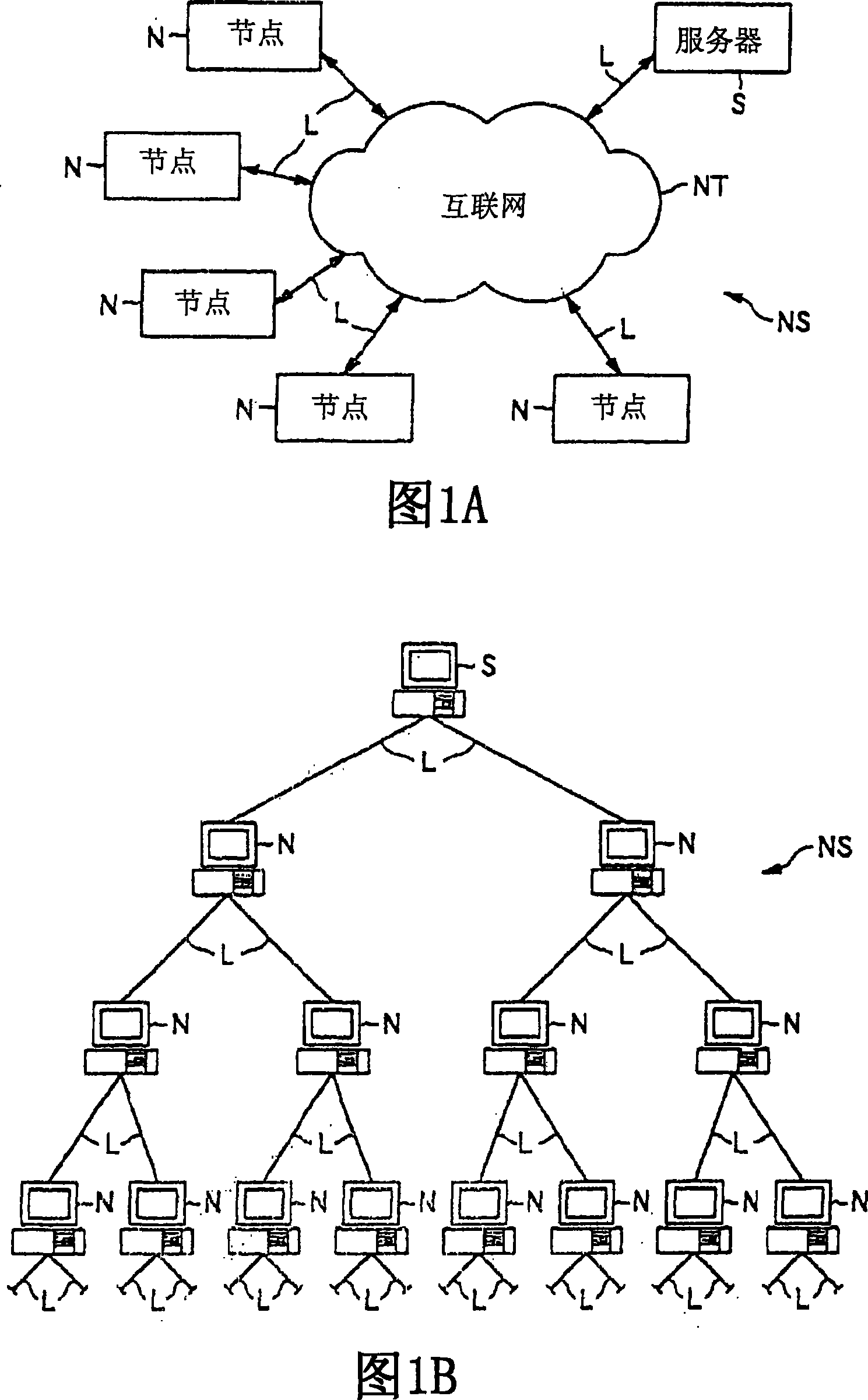
The first embodiment to be described below relates to a case where the present invention is applied to a network control process for controlling a distribution mode of content in a network system in which content is distributed and the The network system includes: a server as a node, which is a distribution device as a distribution source of the content of distribution information; and a plurality of nodes as user terminals connected to include a plurality of levels below the server tree structure.

[0082]

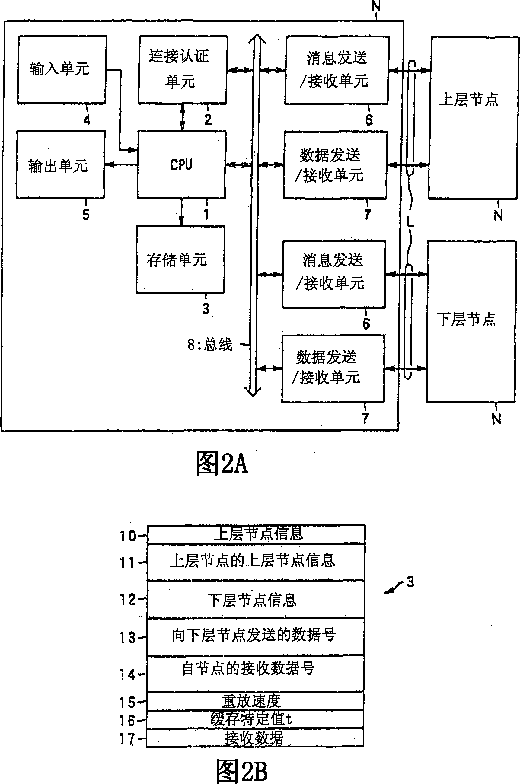
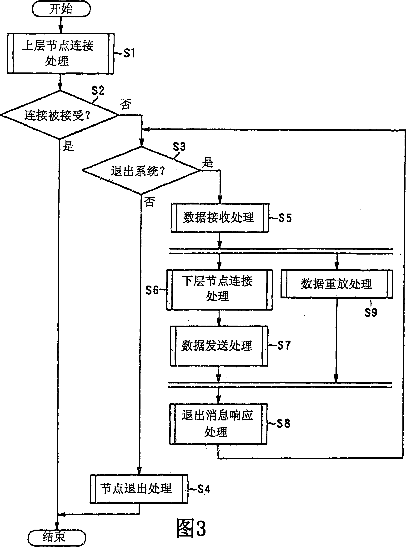
1A and 1B show a schematic structure of a network system according to the first embodiment. 2A and 2B are block diagrams showing detailed structures of nodes included in the network system. 3 to 6 are flowcharts each showing distribution processing performed in a node according to the present invention. 7A to 7C to 13A to 13C specifically show the postin...

no. 2 example

(A) Example

First, a second embodiment according to the present invention will be described with reference to FIGS. 15 to 22A and 22B.

[0179]

Fig. 15 is a block diagram showing a schematic configuration of a network system according to the second embodiment. Fig. 16 is a block diagram showing a general structure of nodes included in the network system. 17A and 17B show the detailed structure of the node. Fig. 18 is a flowchart showing a conventional posting operation in a network system. Fig. 19 is a block diagram showing a schematic structure of a network system after the relay function of some nodes is stopped. 20A, 20B and 20C are flowcharts showing operations in the lower layer nodes when the relay function is stopped. Fig. 21 shows the operation of the lower layer node when the relay function is stopped. 22A and 22B show operations in the revised network system according to the second embodiment.

[0180]

As shown in FIG. 15, the network system NT according ...

no. 3 example

A third embodiment as another embodiment according to the present invention will now be described with reference to FIGS. 23 to 26 .

[0243]

23 and 24 are block diagrams each showing a schematic configuration of a network system according to the third embodiment, and FIGS. 25 and 26 are flowcharts showing operations of the network system.

[0244]

In the second embodiment described above, the case has been described where the relay function in the node is stopped during reception of content distributed via only one line L. In the third embodiment described below, a node is provided in advance with two routes; a main route and a sub route, and receives posted content.

[0245]

As shown in FIG. 23, in a similar manner to the second embodiment, a network system NT2 according to the third embodiment is formed by a tree structure whose vertices are nodes 0-1 as distribution devices. The network system NT2 includes nodes 1-1, 1-2, and 1-3 as nodes constituting the first hiera...


PUM


Abstract

There is provided a network control device capable of surely distributing a content even when a relay function of one of the nodes contained in a network stops, without affecting the process in nodes below the node and while improving the reliability of the network system itself. When controlling a node N contained in a network system NS including a server S and a plurality of nodes N constituting a plurality of hierarchies and connected to one another, wherein a content is distributed from the server S to the respective nodes N, it is checked whether a content relay function in a node located at the uplink with respect to the node N in the content distribution has stopped. When the stop of the relay function is detected, control is performed so that the consumption speed of the content accumulated in the lower node N in the process executed in the node N is smaller than the consumption speed before the relay function has stopped.

Description

technical field [0001] The present invention relates to the technical field of a network control device, a connection mode control device, a network control method, a connection mode control method, a network control program and a connection mode control program. More specifically, the present invention relates to a network control device for controlling a distribution mode of distribution information distributed from a distribution source in a network system while relaying distribution information step by step in relay units that are connected and constitute a multi-stage hierarchy , the technical field of a connection mode control device, a network control method, a connection mode control method, a network control program, and a connection mode control program. Background technique [0002] In recent years, network systems have been widely used as the speed of Internet lines for homes has increased. In the network system, a network is constructed by connecting home p...

Claims


Application Information

Patent Timeline
IPC IPC(8): H04L12/56H04L12/44H04L13/08H04L45/02H04L45/24H04L45/247
CPCY02B60/31
Inventor 日比野义彦清原裕二铃木博明牛山建太郎饭岛康一
Owner BROTHER KOGYO KK
Why Eureka
Try Eureka