Flat panel X-ray imaging device—twin flat detector signal synchronization

a flat-panel x-ray imaging and signal synchronization technology, applied in optics, medical science, instruments, etc., can solve the problems of inability to intuitively or easily determine how much added or reduced kv is needed, the kv voltage is not easily determined, and the system is not easy to move. , to achieve the effect of increasing the risk of personnel involved, increasing the cost and complexity of the system, and reducing the mobility of the system

Active Publication Date: 2018-06-26
SCANFLEX HEALTHCARE
View PDF8 Cites 4 Cited by
  • Summary
  • Abstract
  • Description
  • Claims
  • Application Information

AI Technical Summary

Benefits of technology

[0008]One embodiment of the invention solves this narrowing the area of interest by having an overview of the regulated kV value dependent on previous output and regulating a pulse width, the result is a well regulated and controlled kV output which the user can view and adjust accordingly if needed. By having an adaption unit 120 connecting the various embodiments of the systems results in less cables being needed. In one embodiment, a mobile digital fluoroscopy system, having a mobile X-ray system carrier unit having a first and a second X-ray system each having a transmitter and a receiver, said respective first and second X-ray systems being configured, e.g. by being mounted on a G-arm, to enable X-ray imaging in mutually intersecting planes.
[0015]Another problem with the conventional systems is that the system requires a large amount of cables, thereby increasing cost and complexity of the system, decreasing the mobility of the system and increasing the risk of personnel involved tripping or disconnecting a cord during operation of the system.

Problems solved by technology

A problem with conventional systems is that the value of voltage in kV to energize the X-ray generators for emitting energy as needed in the scan process in order to achieve an as efficient scan as possible is not provided and is not easily determined without time lost in order to calibrate the system.
It is also not intuitive or easily determined how much more added or how much reduced kV is needed in order to have a successful scan.
Another problem is connecting the complex systems without having the carrier of the X-ray systems, e.g. in the form of a G-arm, being too bulky or heavy or with too many cables connecting the apparatus to the control unit and displays.

Method used


Image

  • Flat panel X-ray imaging device—twin flat detector signal synchronization
  • Flat panel X-ray imaging device—twin flat detector signal synchronization
  • Flat panel X-ray imaging device—twin flat detector signal synchronization

Examples


Embodiment Construction

[0049]System Overview

[0050]The present invention concerns an X-ray apparatus configured as a system of components illustrated in the Figures of the drawings, adapted for use in connection with surgical orthopedic operations.

[0051]Embodiments of the invention comprise a mobile G-arm fluoroscopy system provided with flat digital X-ray detectors.

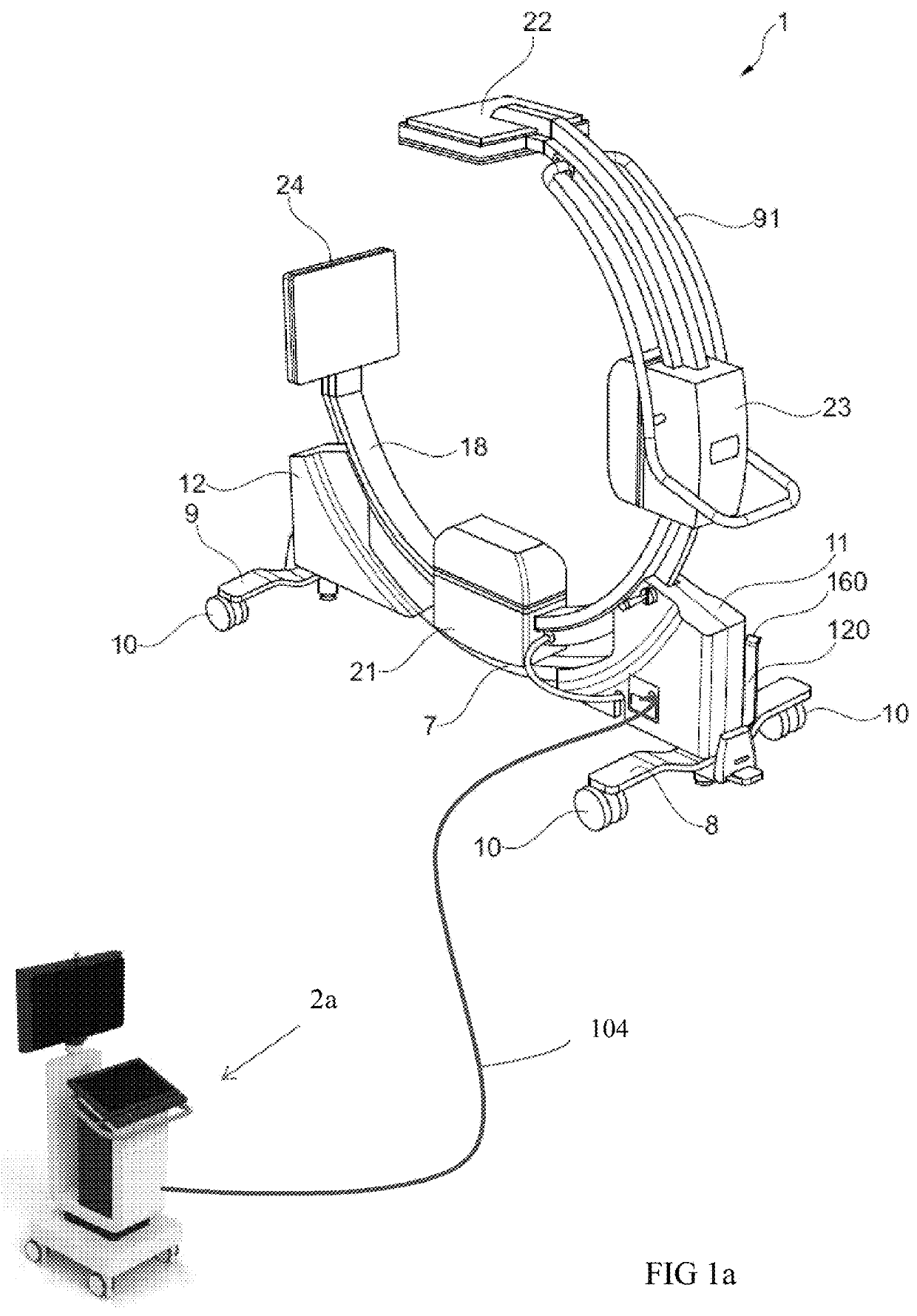
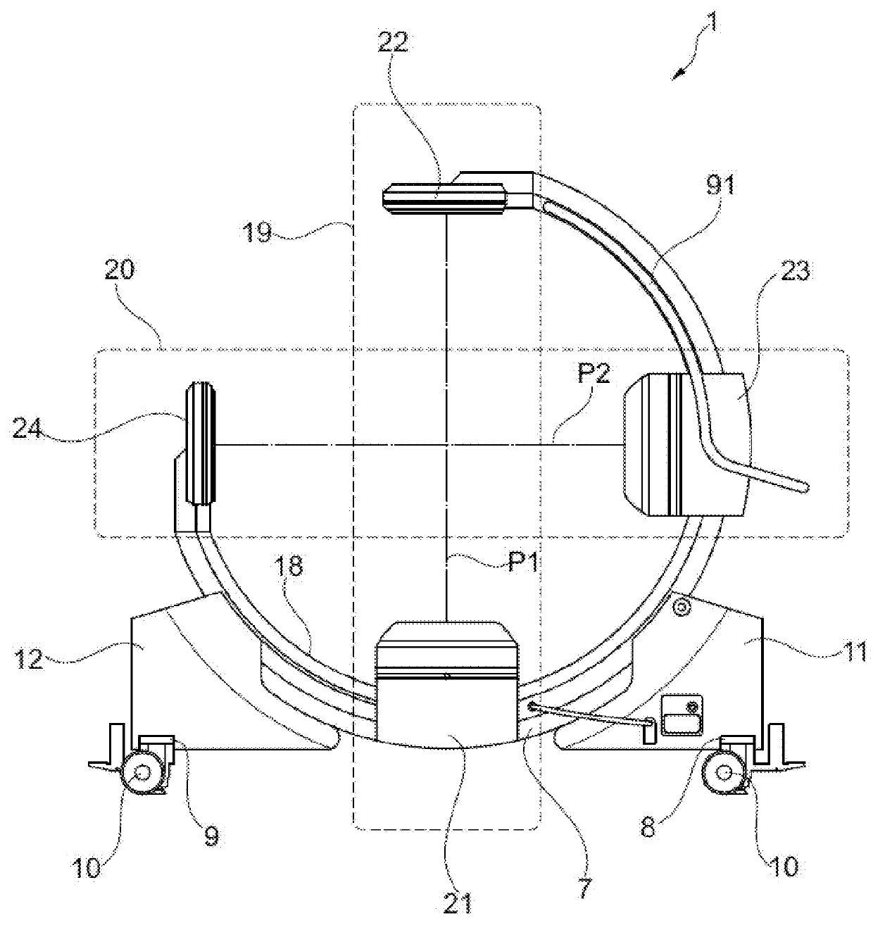
[0052]According to an embodiment, there is provided a mobile digital fluoroscopy system, comprising a mobile unit 1, also called a mobile X-ray system carrier unit 1, having a stand having a G-arm 18 suspended on a chassis frame 7; a first X-ray device 19 mounted on the G-arm 18 to transmit an X-ray beam along a first plane P1, the first X-ray device 19 having a first receiver 22 mounted on the G-arm 18 and a first transmitter 21 mounted on the G-arm 18 opposite said first receiver 22; a second X-ray device 20 mounted on the G-arm 18 to transmit an X-ray beam along a second plane P2 intersecting the first axis P1 of the first X-ray device, the ...


PUM


Abstract

A mobile digital fluoroscopy system comprising a mobile X-ray system carrier unit (1) comprising a first and a second X-ray device (19, 20) each having a transmitter (21, 23) and a receiver (22, 24), wherein said respective first and second X-ray devices (19, 20) are configured to enable X-ray imaging in mutually intersecting planes, a kV unit1012; and; wherein said a mobile control unit (2a) is communicatively coupled to the mobile X-ray system carrier (1) via a cable (150), wherein said mobile control unit (2a) is configured to receive a first set of image data 810 from said kV unit (1012) and sending a control signal to said kV unit (1012) upon completion of receiving of said image data 810, wherein kV unit 1012 is configured to generate a synchronization signal 820 to said transmitters (21, 23) and receivers (22,24) and to send a second set of image data 810 received from receivers (22,24) to the mobile control unit 2a.

Description

FIELD OF THE INVENTION[0001]The present invention relates in general to a preferably mobile digital fluoroscopy system for medical applications operating with an X-ray device mounted to generate X-ray images.[0002]More specifically, the present invention relates to signal synchronization of emitting X-ray radiation pulses and of capturing images receivers in a fluoroscopy system having multiple X-ray devices each provided with a flat digital X-ray detector, and oriented on different axes to provide different views of the location of interest in the patient with the ability to control the area of the patient exposed to the X-ray beam via a user interface.BACKGROUND[0003]In orthopedic surgery environment, there is a need for allowing full access to the operating area with total control at each step. Therefore, X-ray imaging using C-stands or G-stands comprising imaging systems is commonly used, wherein a C-stand only has one X-ray imaging device while a so-called G-stand comprises two...

Claims


Application Information

Patent Timeline
Patent Type & Authority Patents(United States)
IPC IPC(8): A61B6/00H05G1/32G03B42/02
CPCA61B6/487A61B6/4014A61B6/4233A61B6/4266A61B6/4405A61B6/4441A61B6/463A61B6/542A61B6/545A61B6/56A61B6/4482H05G1/32A61B6/467
Inventor NEUMANN, VOLKER
Owner SCANFLEX HEALTHCARE
Why Eureka
Try Eureka