Flat panel X-ray imaging device—twin flat detector architecture

a technology of x-ray imaging and flat detector, which is applied in the field of flat panel x-ray imaging device, twin flat detector architecture, fluoroscopy system, can solve the problems of not intuitive, connecting complex systems without g-arm being too big,

Active Publication Date: 2022-10-04
SCANFLEX HEALTHCARE
View PDF7 Cites 0 Cited by
  • Summary
  • Abstract
  • Description
  • Claims
  • Application Information

AI Technical Summary

Benefits of technology

[0007]The general object of the invention is to provide improvements in a digital fluoroscopy system for medical applications operating with first and second X-ray imaging devices mounted on a G-stand to generate X-ray images along two mutually intersecting axes. The present invention improves the limited space available within a G-arm for a surgeon to operate by separating the functionality of transmitter and receiver parts and distributing them between the X-ray system carrier unit 1 and the mobile control unit 2a. Du to this solution additional space is available within the G-arm at the same time that ergonomics of moving the X-ray system carrier unit is improved.
[0009]One embodiment of the invention solves this narrowing the area of interest by having an overview of the regulated kV value dependent on previous output and regulating a pulse width, the result is a well regulated and controlled kV output which the user can view and adjust accordingly if needed. By having an adaption unit 120 connecting the various embodiments of the systems results in less cables being needed. In one embodiment, a mobile digital fluoroscopy system, having a mobile X-ray system carrier unit having a first and a second X-ray system each having a transmitter and a receiver, said respective first and second X-ray systems being mounted on a G-arm to enable X-ray imaging in mutually intersecting planes, the system further comprising:

Problems solved by technology

A problem with conventional systems is that the value of kV needed in the scan process is not unclear in order to be as efficient scan as possible without time lost in order to calibrate the system.
It is also not intuitive if there is no feedback of the kV used and how much more added kV is needed in order to have a successful scan.
Another problem is connecting the complex systems without having the G-arm being too bulky or heavy or with too many cables connecting the apparatus to the control unit and displays.

Method used


Image

  • Flat panel X-ray imaging device—twin flat detector architecture
  • Flat panel X-ray imaging device—twin flat detector architecture
  • Flat panel X-ray imaging device—twin flat detector architecture

Examples


Embodiment Construction

System Overview

[0042]The present invention concerns an X-ray apparatus configured as a system of components illustrated in the Figures of the drawings, adapted for use in connection with surgical orthopedic operations.

[0043]Embodiments of the invention comprise a mobile G-arm fluoroscopy system provided with flat digital X-ray detectors.

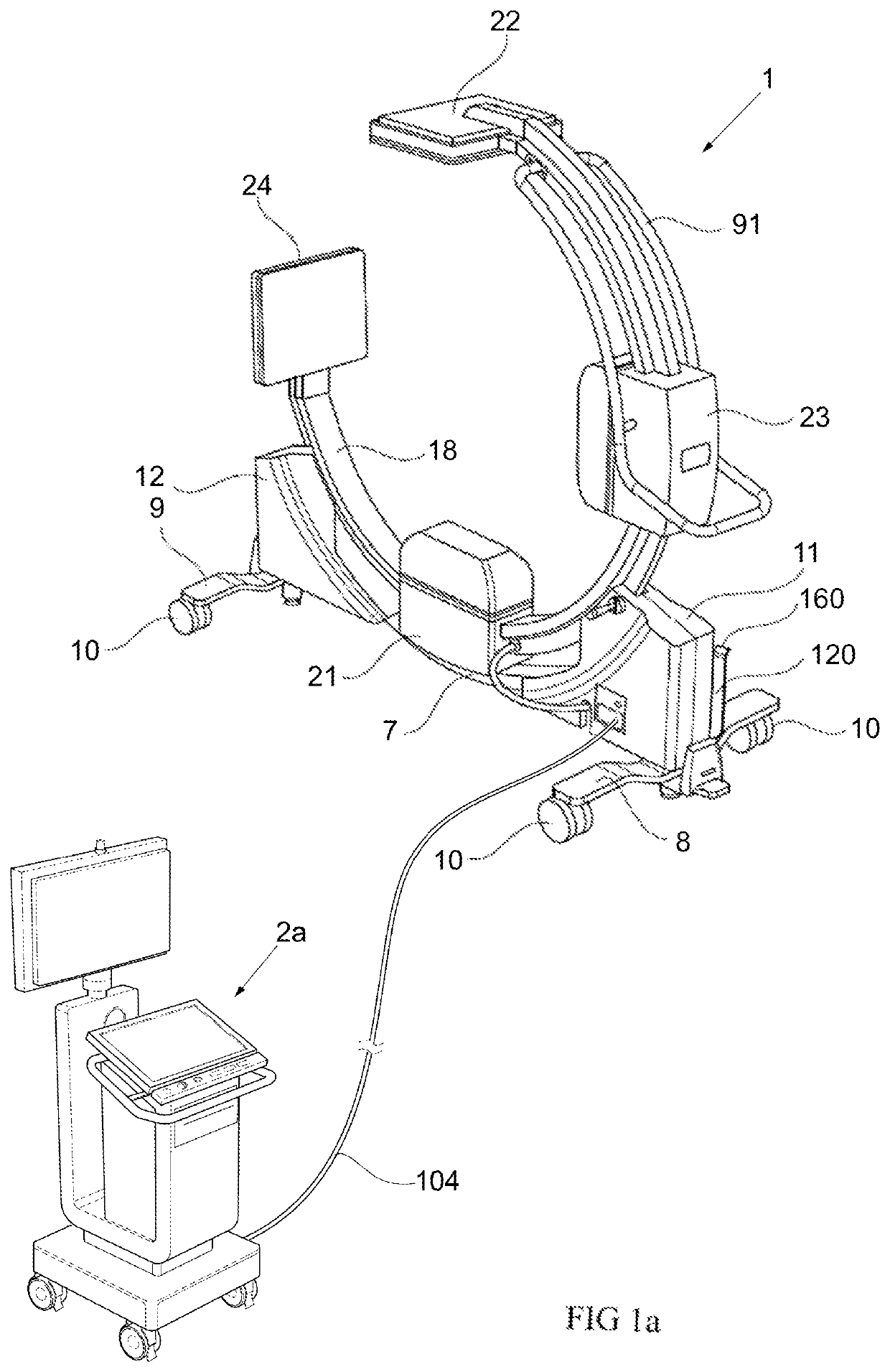
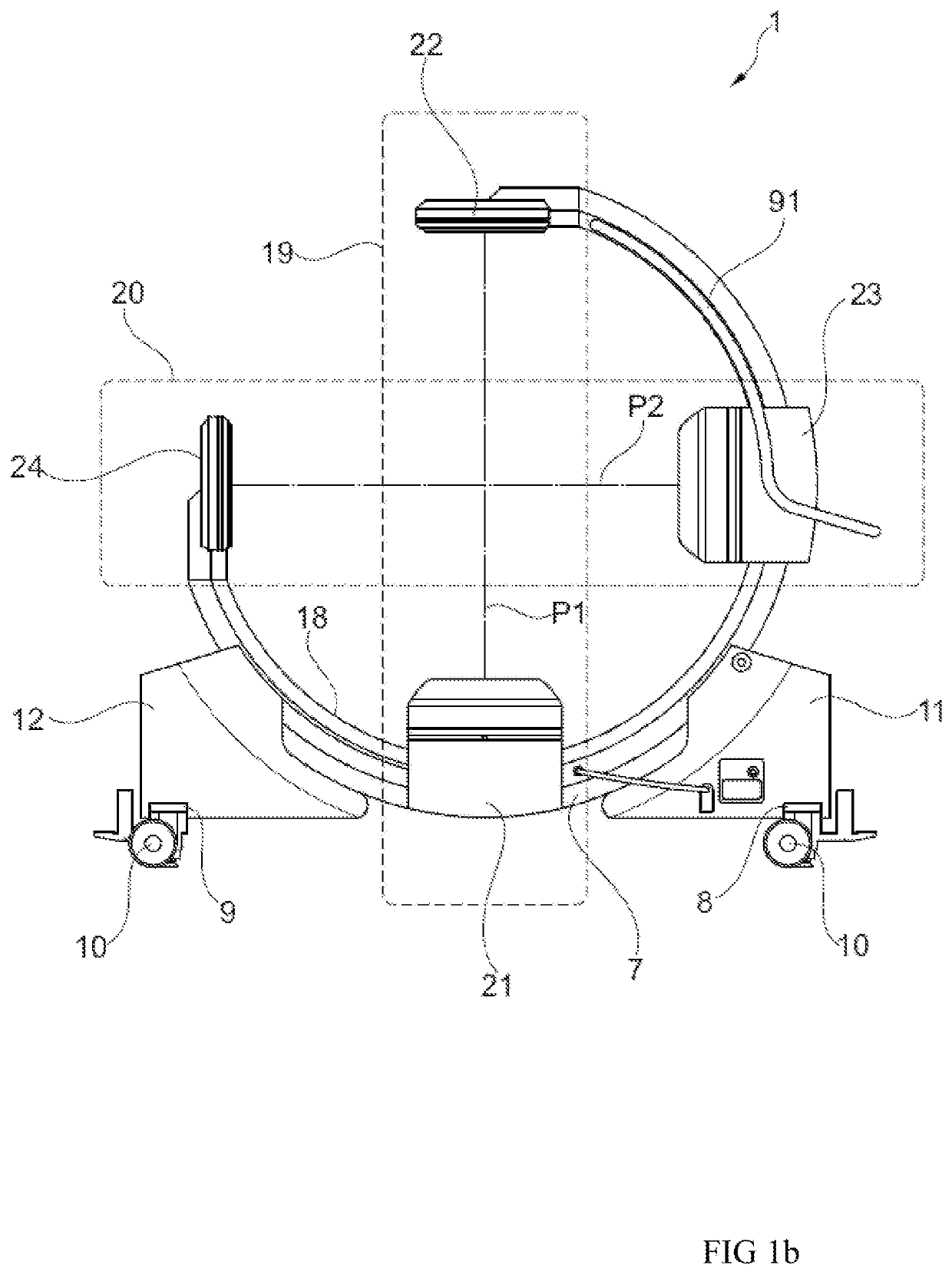
[0044]According to an embodiment, there is provided a mobile digital fluoroscopy system, comprising a mobile unit 1, also called a mobile X-ray system carrier unit 1, having a stand having a G-arm 18 suspended on a chassis frame 7; a first X-ray device 19 mounted on the G-arm 18 to transmit an X-ray beam along a first plane P1, the first X-ray device 19 having a first receiver 22 mounted on the G-arm 18 and a first transmitter 21 mounted on the G-arm 18 opposite said first receiver 22; a second X-ray device 20 mounted on the G-arm 18 to transmit an X-ray beam along a second plane P2 intersecting the first axis P1 of the first X-ray device, the second...


PUM


Abstract

A mobile digital fluoroscopy system is disclosed comprising a mobile X-ray system carrier unit, a mobile control unit and an interconnecting table. The X-ray system carrier unit comprises a kV unit, a x-control unit and a first and a second X-ray system each having a transmitter and a receiver. The respective first and second X-ray systems are configured to be mounted to a G-arm and to enable X-ray imaging in mutually intersecting planes. The mobile control unit comprises a 1st inverter, a 2nd inverter, a 1st transmitter generator, a 2nd transmitter generator and a display system. The kV unit is configured to control transmitters to emit or not to emit X-ray energy, to receive image data from the receivers and to send image data via a network connection in said cable.

Description

FIELD OF THE INVENTION[0001]The present invention relates in general to a preferably mobile digital fluoroscopy system for medical applications operating with an X-ray device mounted to generate X-ray images.[0002]More specifically, the present invention relates to a fluoroscopy system having multiple X-ray devices each provided with a flat digital X-ray detector, and oriented on different axes to provide different views of the location of interest in the patient with the ability to control the area of the patient exposed to the X-ray beam via a user interface, in particular with regards to X-ray system space available within the G-arm, X-ray system maneuverability and transmitter control voltageBACKGROUND[0003]In orthopedic surgery environment, there is a need for allowing full access to the operating area with total control at each step. Therefore, X-ray imaging using C-stands or G-stands comprising imaging systems is commonly used, wherein a C-stand only has one X-ray imaging dev...

Claims


Application Information

Patent Timeline
Patent Type & Authority Patents(United States)
IPC IPC(8): A61B6/00H05G1/32
CPCA61B6/487A61B6/4014A61B6/4266A61B6/4405A61B6/4435A61B6/4441A61B6/4482A61B6/54A61B6/542A61B6/545A61B6/56A61B6/563H05G1/32A61B6/463A61B6/467
Inventor NEUMANN, VOLKER
Owner SCANFLEX HEALTHCARE
Why Eureka
Try Eureka