Multifunctional continuous phase transition extraction apparatus

a multi-functional, continuous phase technology, applied in the direction of solvent extraction, solvent extraction, liquid solution solvent extraction, etc., can solve the problems of low extraction efficiency, inconvenience in filtrating after extraction and recycling solvents, limited kinds of solvents for use, etc., and achieve high efficiency.

Active Publication Date: 2018-07-10
CAO YONG
View PDF17 Cites 0 Cited by
  • Summary
  • Abstract
  • Description
  • Claims
  • Application Information

AI Technical Summary

Problems solved by technology

The solvent leaching is widely used because of its low cost, simple equipment and wide application scope, but it still has some disadvantages such as low efficiency in extraction and inconvenience in filtrating after extraction and recycling solvents.
But the apparatus of reflux extraction adopts spray design with only 0.1 MPa maximum pressure, has limited kinds of solvents for use and limited improvement in efficiency.
First, the extraction has a good performance only in separating the nonpolar substance, but has a poor one in separating the polar substance.
Second, the extraction must be processed in over 20 MPa super high pressure, which limits the amplification of equipment volume.
Third, the extraction has high cost in equipment manufacture and maintenance, which limits the development of this technology and thus its application is limited.
But it is time-consuming, needs a high amount of solvents, and operates intermittently likes conventional solvent extractions.

Method used


Image

  • Multifunctional continuous phase transition extraction apparatus
  • Multifunctional continuous phase transition extraction apparatus

Examples


embodiment 1

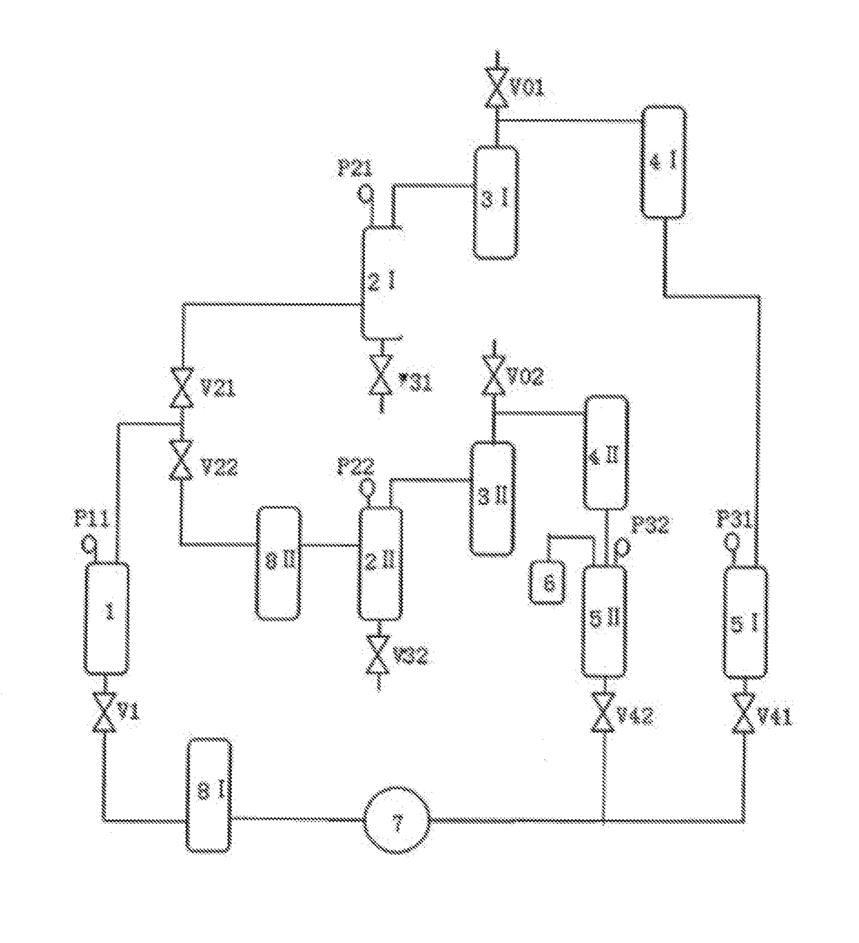
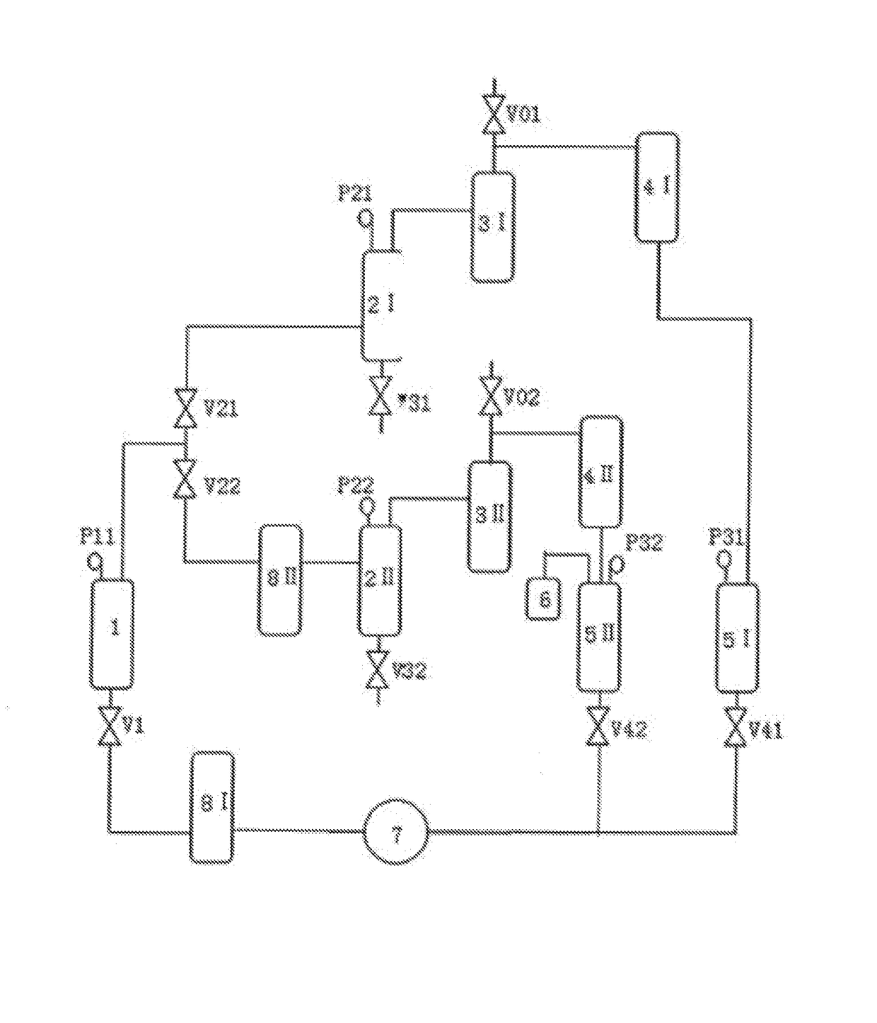
[0030](1) 7 kg camellia oil fruits (smashed to 20 mesh, dried to 5% or less of moisture content) was put into the extraction tank 1. N-butane was forced by the high-pressure pump 7 through the heat exchanger 8 I, and then went into the extraction tank 1 for extraction (temperature 45° C., pressure 0.5 MPa). The solvent together with oil from the extraction tank 1 went into the desorption tank 2 I for desorption (temperature 55° C., pressure 0.25 MPa). The whole extraction time was 50 min. 1.94 KG products were obtained from the first bottom valve V31 of the desorption tank 2 I. The verified extraction yield was 99.3%.

[0031](2) After the oil extraction, it was switched to the loop: the extraction tank 1, the heat exchanger 8 II, the second pressure control valve V22, the second desorption tank 2 II, the second purification column 3 II, the second condenser 4 II, the second solvent tank 5 II, the second valve V42, the high-pressure pump 7, and the heat exchanger 8 I. Methanol was used...

embodiment 2

[0032](1) 10 kg castor seeds were pressed by hydraulic pressure to obtain 3 kg oil. The castor bean meal (smashed to 20 mesh, dried to 5% or less of moisture content) was put into the extraction tank 1. N-butane was forced by the high-pressure pump 7 through the first heat exchanger 8 I, and then went into the extraction tank 1 for extraction (temperature 80° C., pressure 1.0 MPa). The solvent together with oil from the extraction tank 1 went into the first desorption tank 2 I for desorption (temperature 60° C., pressure 0.3 MPa). The whole extraction time was 150 min. 1.97 KG products were obtained from the first bottom valve V31 of the first desorption tank 2 I. The verified extraction yield was 98.5%.

[0033](2) After the oil extraction, it was switched to the loop: the extraction tank 1, the second heat exchanger 8 II, the second pressure control valve V22, the second desorption tank 2 II, the second purification column 3 II, the second condenser 4 II, the second solvent tank 5 II...

example 3

[0034](1) The soybean residue after fermentation for soy sauce (7 kg, smashed to 40 mesh, dried to 5% or less of moisture content) was put into the extraction tank 1. Dimethylmethane was forced by the high-pressure pump 7 through the heat exchanger8 I, and then went into the extraction tank 1 for extraction (temperature 45° C., pressure 1.2 MPa). The solvent together with oil from the extraction tank 1 went into the first desorption tank 2 I to for desorption (temperature 60° C., pressure 0.35 MPa). The whole extraction time was 65 min. 2.02 KG products were obtained from the first bottom valve V31 of the first desorption tank 2 I. The verified extraction yield was 99%.

[0035](2) After the oil extraction, it was switched to the loop: the extraction tank 1, the second heat exchanger 8 II, the second pressure control valve V22, the second desorption tank 2 II, the second purification column 3 II, the second condenser 4 II, the second solvent tank 5 II, the second valve V42, the high-pr...


PUM

PropertyMeasurementUnit
pressureaaaaaaaaaa
pressureaaaaaaaaaa
pressureaaaaaaaaaa

Abstract

A multifunctional continuous phase transition extraction apparatus comprises an extraction system, a desorption system and a solvent recovery system. The extraction system comprises a first heat exchanger and an extraction tank. The desorption system comprises a second heat exchanger, a first desorption tank, a second desorption tank, a first purification column and a second purification column. The solvent recovery system comprises a first condenser, a second condenser, a first solvent tank and a second solvent tank. Two extraction loops can be formed in the present invention. During the overall extraction process, the phase transition process of the extracting agent is real-time and continuous. The extracting agent goes through continuous phase-transitions and is cyclically re-used. The overall process is operated in an airtight and low-pressure condition, and is multifunctional, safe, reliable, and suitable for the extraction for most natural products.

Description

CROSS-REFERENCE TO RELATED APPLICATIONS[0001]The present application is a national phase entry under 35 U.S.C. § 371 of International Application No. PCT / CN2014 / 082107 filed Jul. 11, 2014, which claims priority from Chinese Application Nos. 201310306553.5 filed Jul. 22, 2013 and 201320434302.0 filed Jul. 22, 2013, all of which are hereby incorporated herein by reference.TECHNICAL FIELD[0002]The invention relates to the technical field of the extraction separation, and to a new apparatus of multifunctional continuous phase transition extraction in extraction separation.BACKGROUND[0003]Normally, the common methods for extraction of the natural products are solvent leaching, reflux extraction, supercritical CO2 extraction, subcritical extraction, etc. The solvent leaching is widely used because of its low cost, simple equipment and wide application scope, but it still has some disadvantages such as low efficiency in extraction and inconvenience in filtrating after extraction and recycl...

Claims


Application Information

Patent Timeline
Patent Type & Authority Patents(United States)
IPC IPC(8): B01D11/02B01D11/04C11B1/10B01D3/06B01D3/14C11B1/04
CPCB01D11/0296B01D3/06B01D3/143C11B1/108B01D11/0488C11B1/04C11B1/10B01D11/0284
Inventor CAO, YONGDAI, WEIJIELIU, HANCHAZHANG, YONGGUAN, XIAOSHENGXU, HONGLIU, FEI
Owner CAO YONG
Why Eureka
Try Eureka