Method and system for sensing ingot position in reduced cross-sectional area molds

a technology of cross-sectional area and sensing system, which is applied in the direction of ingot casting plant, manufacturing tools, casting plants, etc., can solve the problems of visual monitoring and subsequent control of the ingot position within the mold, and achieve the effects of small or reduced cross-sectional dimension, high quality, and high quality

Active Publication Date: 2018-07-17
RETECH SYSTEM LLC
View PDF10 Cites 6 Cited by
  • Summary
  • Abstract
  • Description
  • Claims
  • Application Information

AI Technical Summary

Benefits of technology

[0008]This presently-disclosed invention describes a method and system for determining the position of an ingot within a segmented, water-cooled mold surrounded by an induction melting coil. In particular, a mold and coil assembly as disclosed herein is used to produce ingots having a relatively small or reduced cross-sectional dimension. Such ingots can be made of complex reactive or refractory metal alloys such as titanium aluminides or shape-memory nickel-titanium. Induction heating of the mold and its contents can ensure that high quality ingots (ingots that are generally free of internal voids and require minimal post-formation surface clean-up) can be produced. In part, production of high quality ingots is aided by ensuring that the top of the ingot is consistently located within an optimum zone of the mold for melting. In such systems employing a small or reduced cross-sectional area, however, there can be limited view angles within a vacuum metallurgical chamber, rendering visual monitoring and subsequent control of the ingot position within the mold problematic. The present disclosure provides for structure and means to sense the ingot position within the mold by monitoring the current amplitude or current frequency in the induction melting coil (that is connected to an induction power supply) and in the tuning capacitor(s). The induction melting coil current is calibrated for optimum melting conditions. As additional material is added to the top of the mold, the ingot is moved to maintain the induction melting coil current within an acceptable range.
[0012]The heating induction coil and a high frequency power supply are electrically connected to a capacitor which is operable to tune the electrical circuit comprised of the induction coil, the mold and its contents, the capacitor, and the power supply to an optimum power level for melting within the mold. Further, the sense coil can be configured to detect electrical current in a conductor between the heating induction coil and the capacitor, such that the electrical current flowing through the induction melting coil and the capacitor induces a proportional current or frequency in the sense coil circuit. In other aspects, the sense coil can be connected in series with an electronic position controller that is configured to measure changes in electrical current detected by the sense coil. The method can further include: the electronic position controller converting the current detected in the sense coil into an electrical control signal; instructing an ingot position actuator to move the ingot within the segmented mold proximate to the heating induction coil; and maintaining the top of the ingot in a molten state. In some aspects, the electronic position controller can instruct the ingot position actuator via operator interaction. In other aspects, the electronic position controller can instruct the ingot position actuator via an automatic feedback loop. The method can further include melting metal and / or alloy in a primary melting vessel that is configured to pour a portion of molten metal and / or alloy into the top of the segmented mold. In other aspects, the method can include using a primary feeder, configured to deliver feed material in solid form into the top of the segmented mold. In other aspects, the electronic control signal can be used to adjust the power supplied to the heating induction coil and thereby adjust the degree of heating of an ingot within the mold. Further, the pour rate of molten metal and / or alloy into the segmented mold can be adjusted according to the determined position of the ingot within the segmented mold. Finally, the method can further include withdrawing the ingot from the segmented mold, where the ingot formed can have a reduced cross-sectional area.

Problems solved by technology

In such systems employing a small or reduced cross-sectional area, however, there can be limited view angles within a vacuum metallurgical chamber, rendering visual monitoring and subsequent control of the ingot position within the mold problematic.

Method used


Image

  • Method and system for sensing ingot position in reduced cross-sectional area molds
  • Method and system for sensing ingot position in reduced cross-sectional area molds
  • Method and system for sensing ingot position in reduced cross-sectional area molds

Examples


Embodiment Construction

[0019]Throughout this description for the purposes of explanation, numerous specific details are set forth in order to provide a thorough understanding of the many embodiments disclosed herein. It will be apparent, however, to one skilled in the art that the many embodiments may be practiced without some of these specific details. In other instances, known structures and devices are shown in diagram or schematic form to avoid obscuring the underlying principles of the described embodiments.

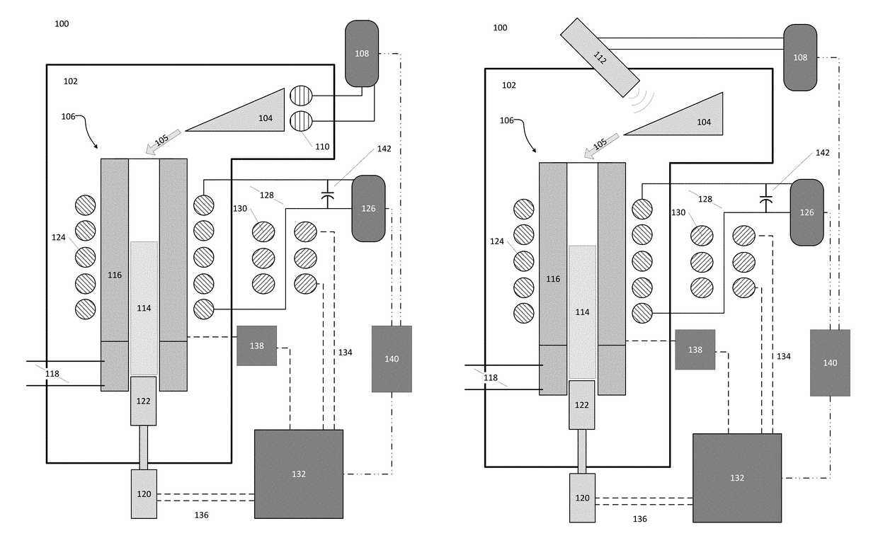
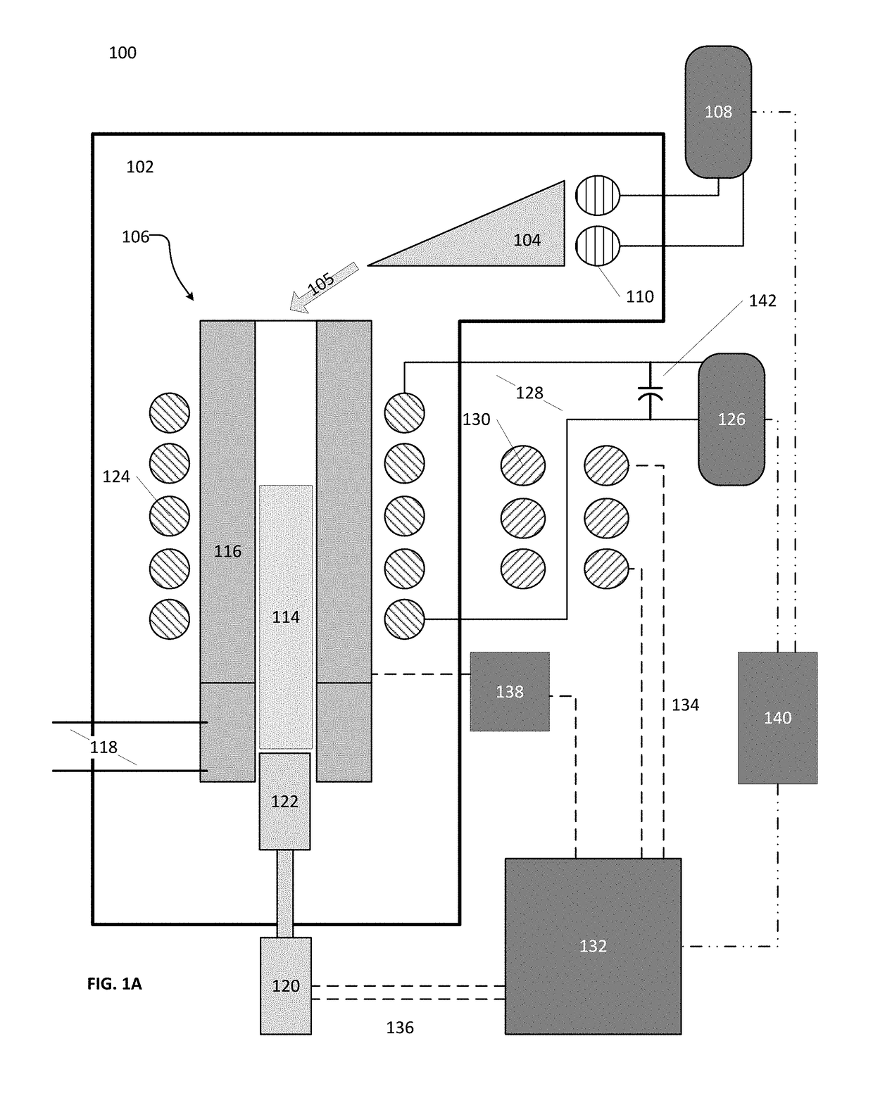
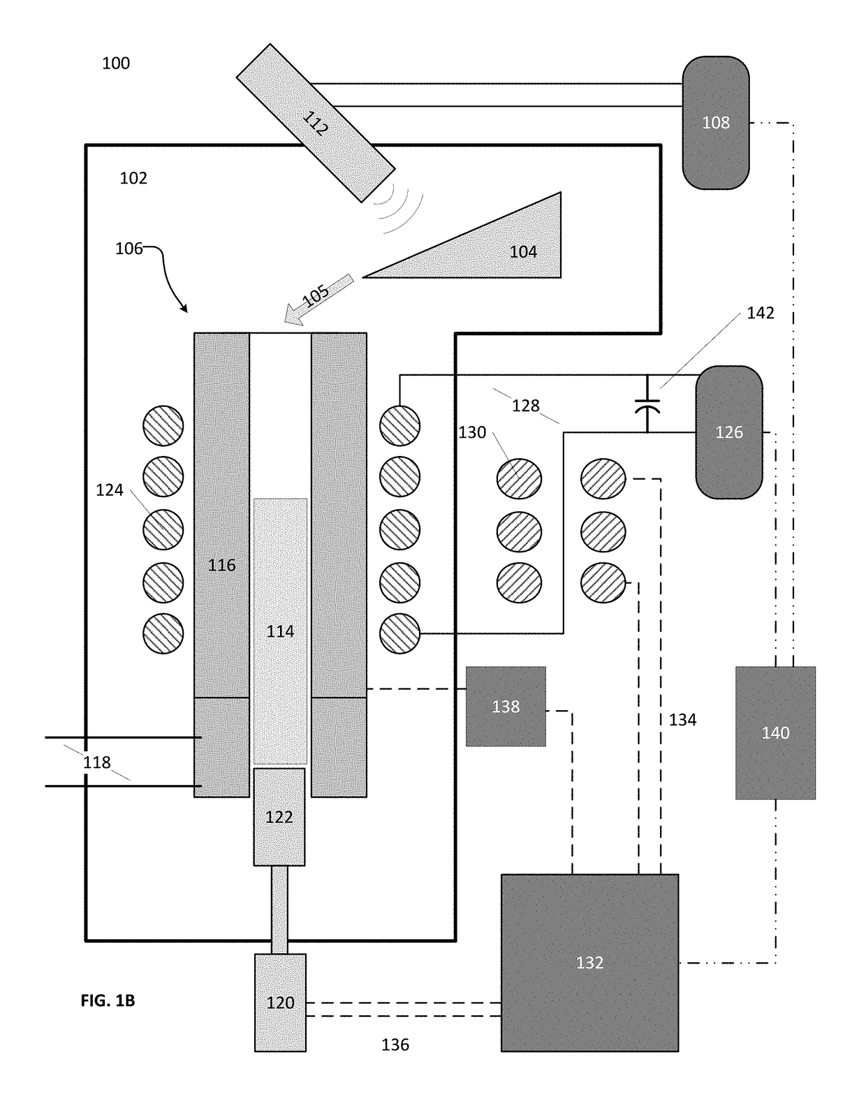
[0020]The present disclosure relates to a system and method of determining the position of an ingot within a mold of a melting system, particularly a vacuum metallurgical melting furnace system, where the ingot cannot be readily observed due to the construction, configuration, and / or other design requirements of the mold as a part of the system. Exemplary embodiments provide a system and method, particularly including an inductive sensory system, for determining the position of an ingot within a s...


PUM

PropertyMeasurementUnit
areaaaaaaaaaaa
diameteraaaaaaaaaa
diameteraaaaaaaaaa

Abstract

A system and method for sensing the position of an ingot within a segmented mold of a vacuum metallurgical system. An inductive sensory system measures the variations in current between a power source and load of an induction heating coil. The system and method is particularly suitable for determining the position of an ingot within a melting system mold where the mold has a relatively reduced or small cross-sectional area.

Description

CROSS-REFERENCE TO RELATED APPLICATIONS[0001]N / ABACKGROUND OF THE INVENTION[0002]In industry, vacuum metallurgical melting systems have been built and operated to produce high quality ingots of reactive or refractory metals and / or their alloys in a single operational process directly from raw materials. In some such systems, raw materials can be provided into an open-top and open-bottom mold, having an heating induction coil surrounding at least part of the mold. The raw materials (or feed material) can be metals such as titanium, zirconium, nickel, cobalt, and / or their alloys, and can be provided into a mold of a vacuum metallurgical system in solid or molten form. When rendered into molten form, these metals can be contaminated by the oxide refractories generally used to make induction melting crucibles; therefore, to avoid contamination, these metals are typically melted in water-cooled copper vessels, although this melting technique is only about 25% efficient thermally.[0003]Re...

Claims


Application Information

Patent Timeline
Patent Type & Authority Patents(United States)
IPC IPC(8): B22D11/20B22D11/041B22D11/14B22D11/18B22D7/00B22D9/00
CPCB22D11/20B22D7/005B22D9/003B22D11/041B22D11/141B22D11/18
Inventor HAUN, ROBERT E.MEESE, PAUL G.
Owner RETECH SYSTEM LLC
Why Eureka
Try Eureka