Low speed heading measurement

a technology of low speed and heading measurement, applied in the direction of vehicle position/course/altitude control, process and machine control, instruments, etc., can solve the problems of equipment adding significant cost, increasing the error of heading measurement, so as to improve the accuracy of navigation system, accurate heading measurement, and improve the effect of steering control

Active Publication Date: 2018-07-17
LEADER TECH
View PDF13 Cites 4 Cited by
  • Summary
  • Abstract
  • Description
  • Claims
  • Application Information

AI Technical Summary

Benefits of technology

[0007]It is a further object, feature, or advantage to provide for accurate heading measurements, even at low speeds.
[0008]It is a still further object, feature, or advantage to improve accuracy of a navigation system.
[0009]Another object, feature, or advantage is to improve steering control.
[0010]Yet another object, feature, or advantage is to provide improved heading measurement while only using a single antenna GPS (or other Global Navigation Satellite System (GNSS)).
[0011]A still further object, feature, or advantage is to produce a more accurate heading determination when a vehicle starts up.
[0012]One or more of these and / or other objects, features, or advantages of the present invention will become apparent from the specification and claims that follow. The present invention is not to be limited to or by these objects, features, and advantages. It is to be further understood that different embodiments may have different objects, features, or advantages and no single embodiment need meet each and every object, feature, or advantage provided herein.

Problems solved by technology

Traditional GPS receivers produce a heading measurement with every GPS update, but the error of the heading measurement increases dramatically as vehicle speed falls below 1 mph and approaches zero.
Where a single antenna GPS is used, heading measurement becomes very noisy as the speed drops below about 1 mph.
Although a dual antenna GPS system may be used to provide a more accurate heading measurement at low and zero speed, the equipment adds significant cost.

Method used


Image

  • Low speed heading measurement
  • Low speed heading measurement
  • Low speed heading measurement

Examples


examples 1

B. Method Examples 1

[0033]A first concept of this invention is relatively simple: a new heading will not be calculated from the GPS coordinates until there has been a sufficient change in position to allow a calculation with acceptable error. To begin, the current GPS coordinates are stored in memory. Then at each GPS update, the change in position relative to the stored GPS coordinates is determined. If the change in position is less than a desired threshold, then the heading is not calculated using the new GPS position. When at a GPS update, the change in position relative to the stored GPS coordinates exceeds a threshold, a new heading is calculated using the current and stored GPS positions. The stored GPS position will then be updated.

[0034]A problem with this approach is that at very low speeds it may be several GPS update periods until a new heading is determined. If the vehicle is being steered in a tight turn during this time, the heading measurement will lag the actual hea...

example 2

C. Method Example 2

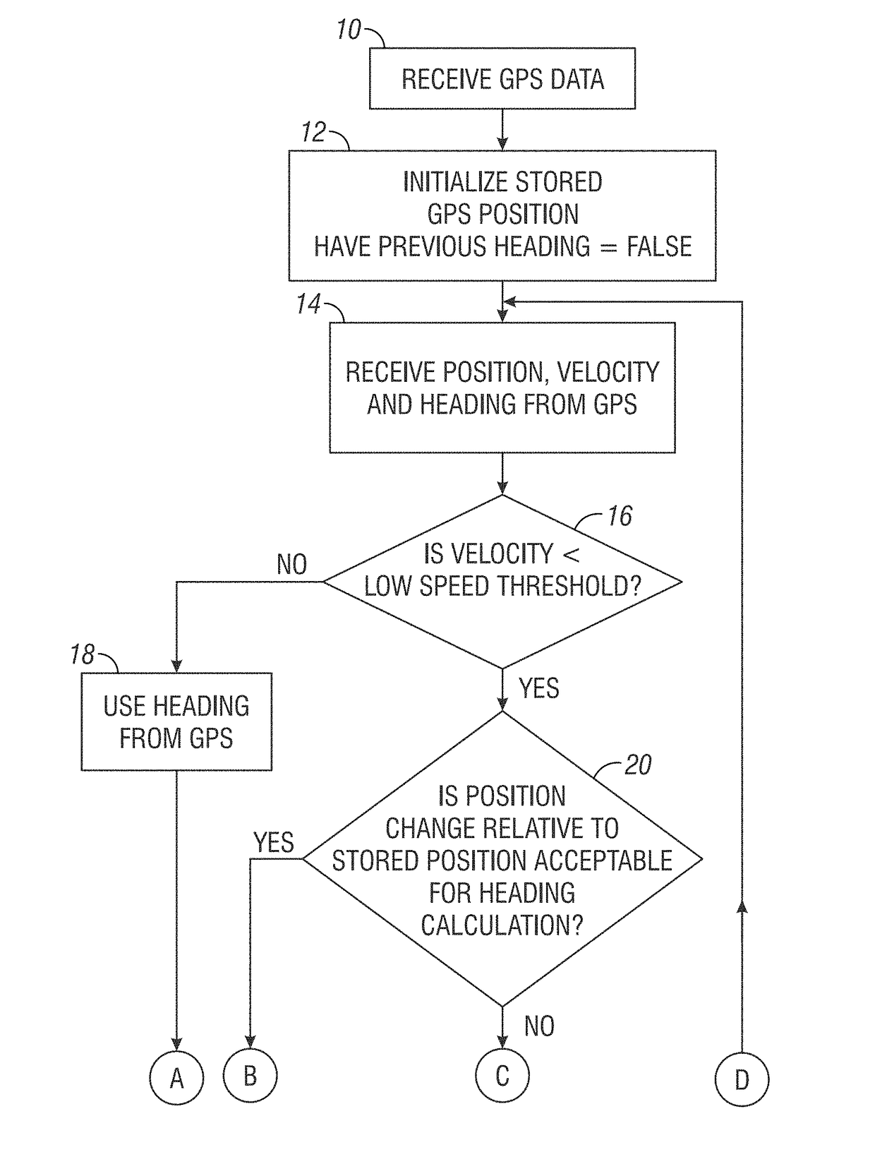
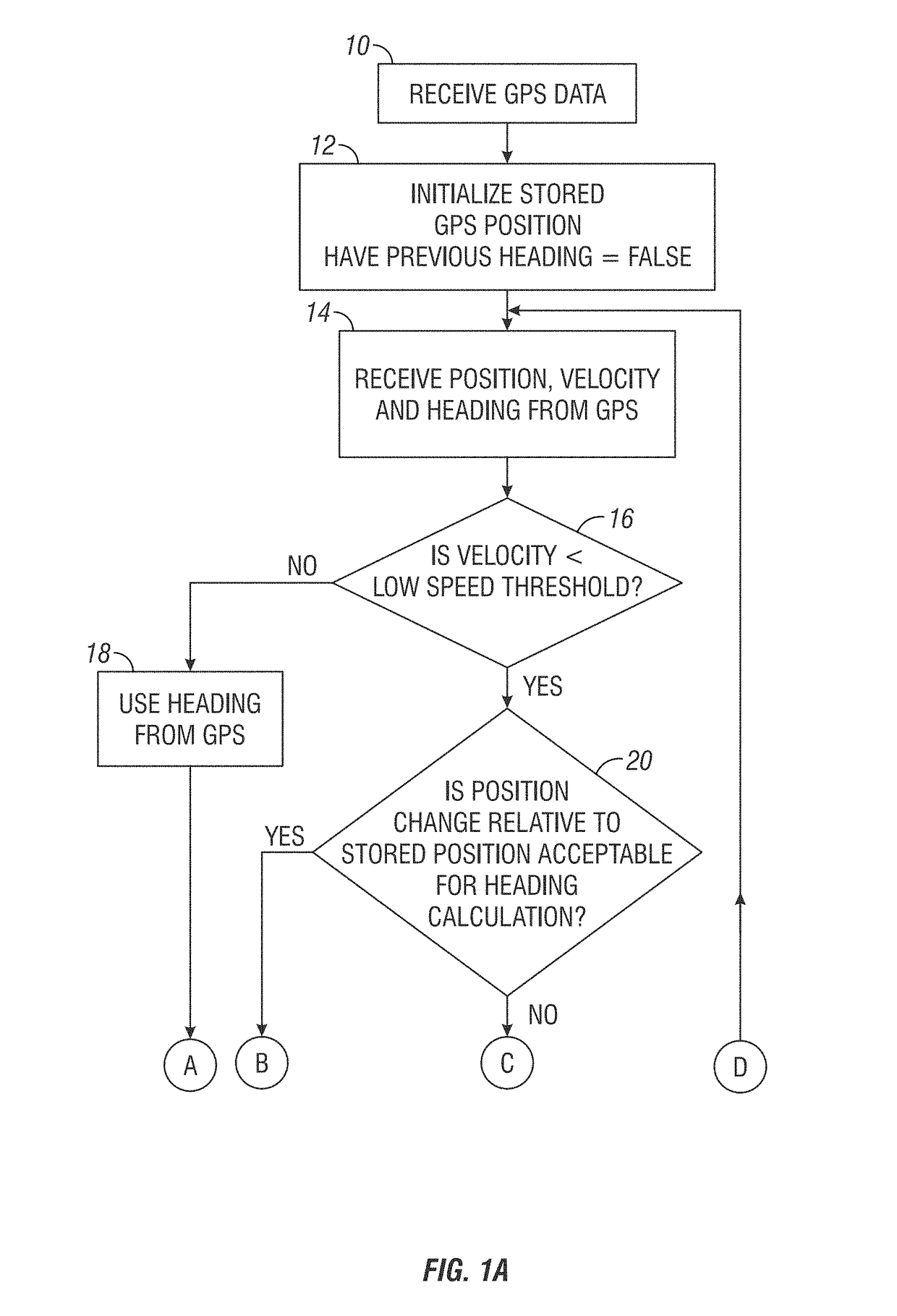
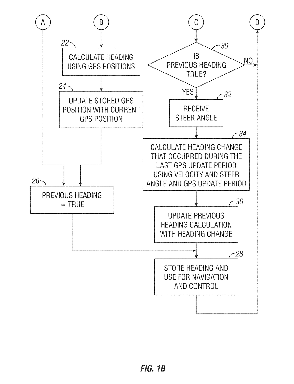
[0040]FIG. 1A and FIG. 1B illustrate a flow diagram of one example of a method for determining heading. The method allows for the heading from the GPS to be used when not at low speed. If at a low speed then instead of using the heading from the GPS, a heading is calculated. Under one set of conditions the heading can be calculated from GPS positions, under another set of conditions a heading change can be calculated and the previous heading calculation can be updated.

[0041]In step 10 GPS data is received. In step 12 an initialization is performed to initialize the stored GPS position and set the flag Have Previous Heading to false. In step 14 position, velocity and heading from the GPS is received. In step 16 a determination is made as to whether the velocity is less than a low speed threshold. If not, then in step 18 the heading from the GPS will be used and then in step 26 (See FIG. 1B) the Have Previous Heading flag is set to true.

[0042]Returning to FIG. 1A, s...

example 3

D. Method Example 3

[0043]FIG. 2A and FIG. 2B illustrate a flow diagram for an alternative process. The process shown in FIGS. 2A and 2B is similar to that shown in FIG. 1A and FIG. 1B except that the heading change is calculated in a different manner. In FIG. 2B, step 30 a determination is made as to whether the flag Have Previous Heading is true or not. If it is, then in step 33 the yaw rate is received. Next, in step 35, the heading change is calculated from the yaw rate and the GPS update period.

E. System Example 1

[0044]FIG. 3 illustrates a block diagram of agricultural equipment 30 configured with low speed heading measurement. A GPS or other location receiver 32 is shown. Information from the GPS receiver may include latitude and longitude, velocity, and heading. Instead of using latitude and longitude directly, the processor may convert latitude and longitude into X, Y coordinates or into another coordinate system. Also, although velocity may be provided from the GPS receiver ...


PUM


Abstract

Methods, apparatus, and systems for use in agricultural equipment with automatic steering control. One method includes the steps of calculating a heading to provide greater accuracy than heading information obtained from the GNSS system or calculated in an equivalent manner using GNSS locations at successive sample periods and using the heading in providing automatic steering control, swath control, or rate control of planting, spraying, or other application functions for the agricultural equipment.

Description

CROSS-REFERENCE TO RELATED APPLICATIONS[0001]This application claims the benefit of Provisional Application U.S. Ser. No. 62 / 117,510, filed Feb. 18, 2015, all of which is herein incorporated by reference in its entirety.FIELD OF THE INVENTION[0002]The present invention relates to agricultural equipment with automatic steering control.BACKGROUND OF THE INVENTION[0003]Agricultural equipment with automatic steering control requires a constantly updated heading measurement for the navigation system. Traditional GPS receivers produce a heading measurement with every GPS update, but the error of the heading measurement increases dramatically as vehicle speed falls below 1 mph and approaches zero. This is because the heading measurement is based on the change in vehicle position from one GPS update to the next, and as speed approaches zero, the change in vehicle position during the GPS sample period becomes small in relation to GPS measurement error. Discussion of such things as automatic ...

Claims


Application Information

Patent Timeline
Patent Type & Authority Patents(United States)
IPC IPC(8): B62D6/00B62D11/00G01S19/42A01B69/04
CPCG01S19/42A01B69/008G05D1/0278G05D2201/0201G01S19/39G01S19/52G01S19/396
Inventor SCHNEIDER, MICHAELWILLETT, DAVE
Owner LEADER TECH
Why Eureka
Try Eureka