
Pseudorandom PWM variation based on motor operating point

a technology of motor operating point and pseudorandom sequence, applied in the direction of torque ripple control, electric energy management, transportation and packaging, etc., can solve the problems of inconsistent performance under variable operating conditions using pseudorandom sequence as in the prior art, and achieve the effect of reducing audible noise and switching losses

Active Publication Date: 2018-07-17
FORD GLOBAL TECH LLC
View PDF10 Cites 2 Cited by
  • Summary
  • Abstract
  • Description
  • Claims
  • Application Information

AI Technical Summary

Benefits of technology

The invention is about an electric drive system for a vehicle. It uses a special inverter circuit to create a multi-phase AC drive signal for the vehicle's electric motor. The system also includes a control mechanism that monitors the performance of the motor and adjusts the driving signal to ensure it runs optimally. The control mechanism has pre-defined settings for different driving situations, and it uses one of these settings for a specific motor operating point. The system also uses a memory to store sequences of driving signals optimized for each driving situation, reducing noise and power losses. The control mechanism then generates the driving signal based on the identified operating situation. Overall, this invention helps improve the efficiency and performance of electric drives for vehicles.

Problems solved by technology

The use of a pseudorandom sequence as in the prior art has provided inconsistent performance under variable operating conditions because the acoustic properties and behavior of an electric drive system varies according to vehicle operating point (e.g., as defined by the drive's torque, speed, and voltage).

Method used


Image

  • Pseudorandom PWM variation based on motor operating point
  • Pseudorandom PWM variation based on motor operating point
  • Pseudorandom PWM variation based on motor operating point

Examples


Embodiment Construction

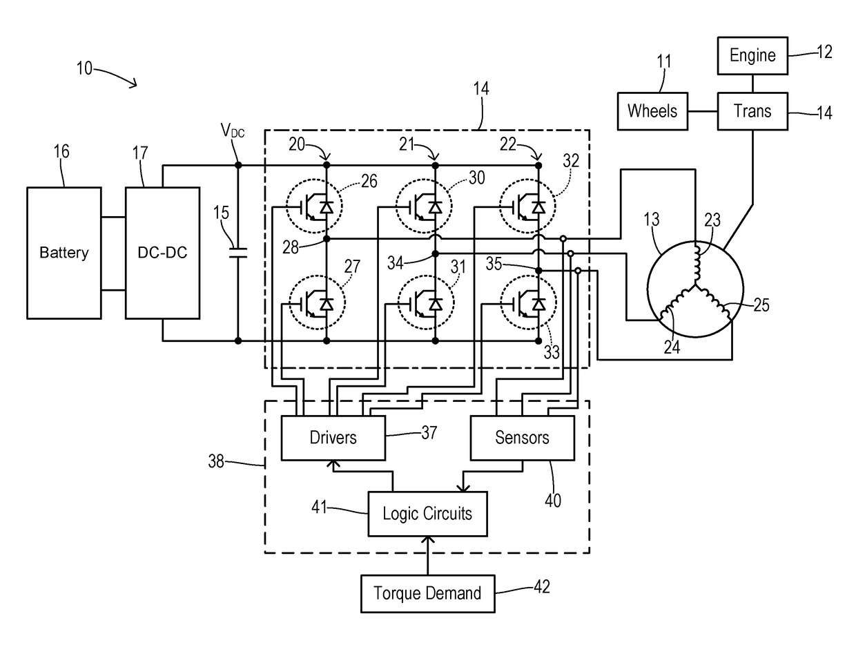
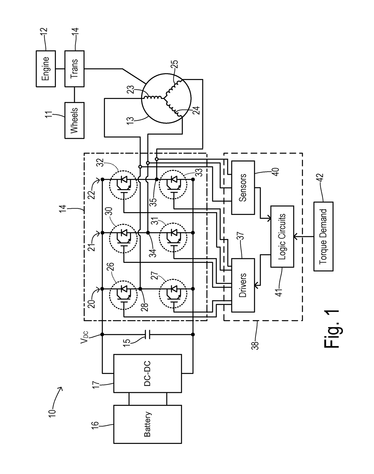
[0023]FIG. 1 shows a hybrid electric vehicle 10 as one type of vehicle for implementing a PWM variation of the present invention. Vehicle wheels 11 may be driven by an internal combustion engine 12 and / or by a traction motor 13 via a transmission 14. For providing electric propulsion, motor 13 may be driven via an inverter switching bridge 15 that receives a DC link voltage at a DC link capacitor 16. The DC link voltage may result from conversion of DC power from a battery pack 17 by a converter 18 as known in the art.

[0024]Inverter 15 includes phase legs 20, 21, and 22 coupled to motor phase windings 23, 24, and 25. Phase leg 20 has an upper switching device 26 and a lower switching device 27 connected in series across DC link 16 and providing a junction 28 between devices 26 and 27 which is connected to winding 23 of motor 13. Similarly, phase leg 21 his upper switching device 30 and lower switching device 31, while phase leg 22 has upper switching device 32 and lower switching de...


PUM


Abstract

An electric drive for a vehicle uses an inverter circuit configured to provide a multi-phase AC drive signal to an electric machine according to a PWM drive signal. A PWM controller monitors an operating point of the electric drive and is configured to identify an operating region of the electric drive from a plurality of predetermined regions in response to the monitored operating point. A sequence memory stores a plurality of sequences, each sequence optimized for a respective one of the predetermined regions to reduce audible noise and switching losses. The PWM controller generates the PWM drive signal according to a respective sequence corresponding to the identified operating region. Thus, the reduction of audible noise and switching losses is optimized based on torque and / or speed of the motor.

Description

CROSS REFERENCE TO RELATED APPLICATIONS[0001]Not Applicable.STATEMENT REGARDING FEDERALLY SPONSORED RESEARCH[0002]Not Applicable.BACKGROUND OF THE INVENTION[0003]The present invention relates in general to power converters including inverters for an electric drive system of an electrified vehicle, and, more specifically, to variation sequences of a pulse-width modulation signal which reduce noise and vibrations associated with the electric drive system.[0004]Electric vehicles, such as hybrid electric vehicles (HEVs), plug-in hybrid electric vehicles (PHEVs), and battery electric vehicles (BEVs), use inverter-driven electric machines to provide traction torque. A typical electric drive system includes a DC power source (such as a battery pack or a fuel cell) coupled by contactor switches to a variable voltage converter (VVC) to regulate a main bus voltage across a main DC linking capacitor. An inverter is connected between the main buses for the DC link and a traction motor in order ...

Claims


Application Information

Patent Timeline
Patent Type & Authority Patents(United States)
IPC IPC(8): H02K29/06H02P6/10
CPCH02P6/10H02P27/085B60L15/2045B60L2240/421B60L2240/423B60L2240/429B60L2270/142Y02T10/64Y02T10/72
Inventor WOLF, CHRISTOPHER M.DEGNER, MICHAEL W.
Owner FORD GLOBAL TECH LLC
Learn More