Cantilevered rotor pump and methods for axial flow blood pumping

a rotor pump and cantilever technology, applied in the field of mechanical circulatory support systems, can solve the problems of heart failure, inability to pump enough blood to your body, etc., and achieve the effect of improving the design of the rotor

Active Publication Date: 2018-07-24
TC1 LLC
View PDF58 Cites 14 Cited by
  • Summary
  • Abstract
  • Description
  • Claims
  • Application Information

AI Technical Summary

Benefits of technology

[0008]In one aspect, blood pumps having improved rotor designs that are supported by mechanical bearings that avoid contact with blood are described herein. In some embodiments, such improved blood pumps include: a pump housing defining a blood flow passage; a rotor including a rotatable shaft and one or more rotor blades extending laterally from the rotatable shaft within the blood flow path to facilitate flow of blood upon rotation of the rotor; and a rotation means adapted for driving rotation of the rotatable shaft. Advantageously, the rotor can be rotatably coupled to the housing through a sealed mechanical bearing that remains outside the blood flow path such that blood contact with the bearing is avoided, thereby avoiding formation of thrombus on the bearing assembly and avoiding the need for washing or flushing the bearing with blood fluid or saline fluid. Typically, the rotation means includes a stator motor and the rotatable shaft includes a number of magnetic elements driven by the stator. In some embodiments, the bearing assembly is rotatably coupled with the rotor shaft at or near the proximal end of the rotor shaft that extends outside of the blood flow path while a distal portion of the rotor shaft remains within the blood flow path and free from attachment to the pump housing such that the mechanical bearing provides cantilevered support of the rotor during operation.
[0012]In another aspect, the sealed mechanical bearing assembly includes one or more radial bearings. The one or more radial bearings may be selected to have an axial thickness or width that extends along a longitudinal axis of the rotor. The radial bearing may be of a metallic (e.g. stainless steel) and / or a ceramic construction. The bearing assembly may include a lubricant, such as an oil-based or silicone lubricant, to facilitate movement of the radial bearings within the assembly. This aspect allows the bearing to withstand greater deflecting forces and / or to apply a greater reactive torque to the proximal portion of the rotor shaft so as to maintain a position and / or alignment of the rotor during operation. In some embodiments, the one or more radial bearings have a total axial width between 0.01″ and 1″, or more preferably between 0.050″ and 0.500″. The length of the rotor may be between 0.250″ to 3.500″. In some embodiments, the pump housing is substantially rigid and the rotor blades are disposed entirely within the blood flow path defined within the pump housing. In some embodiments, the rotor is driven by a drive shaft. The mechanical bearing may be incorporated into a rear cover that interfaces with the pump housing and may also be of rigid construction. In some embodiments, the drive shaft is substantially rigid and may be entirely internal to the blood pump, such that the shaft is driven without any need for motors or cables external to the blood pump to drive the rotor. In some embodiments, the rotor extends directly from the mechanical bearing to the rotor blades within the blood pump.
[0014]In some embodiments, such devices are configured with rotors dimensioned to provide a suitable blood flow rate to provide ventricular assist while rotational speeds of the rotor are within a range of about 1,000 to 10,000 rpm, such as within a range of about 1,000 to 5,000 rpm. In some examples, suitable blood flow rates are any blood flow rate up to 10 L / min, and are often within a range of blood flows such as between 1 L / min to 12 L / min, between 3 L / min to 10 L / min, and 4 L / min to 6 L / min. Such rotors can be controlled so as to provide constant flow rates or variable flow rates as needed. It is appreciated that such pump devices can be controlled so as to provide lower blood flow rates as needed, for example depending on the level of assist required by the blood flow pump.

Problems solved by technology

People with heart failure often have shortness of breath and fatigue.
Years of living with blocked arteries or high blood pressure can leave your heart too weak to pump enough blood to your body.
As symptoms worsen, advanced heart failure develops.
While blood pumps have been effective for many patients, because patients using such devices are living longer, further improvements that prolong the effectiveness and lifetime of such blood pump devices are desired.
One challenge frequently encountered in axial blood pumps is the development of thrombus in the bearing assemblies supporting the rotor.

Method used


Image

  • Cantilevered rotor pump and methods for axial flow blood pumping
  • Cantilevered rotor pump and methods for axial flow blood pumping
  • Cantilevered rotor pump and methods for axial flow blood pumping

Examples


Embodiment Construction

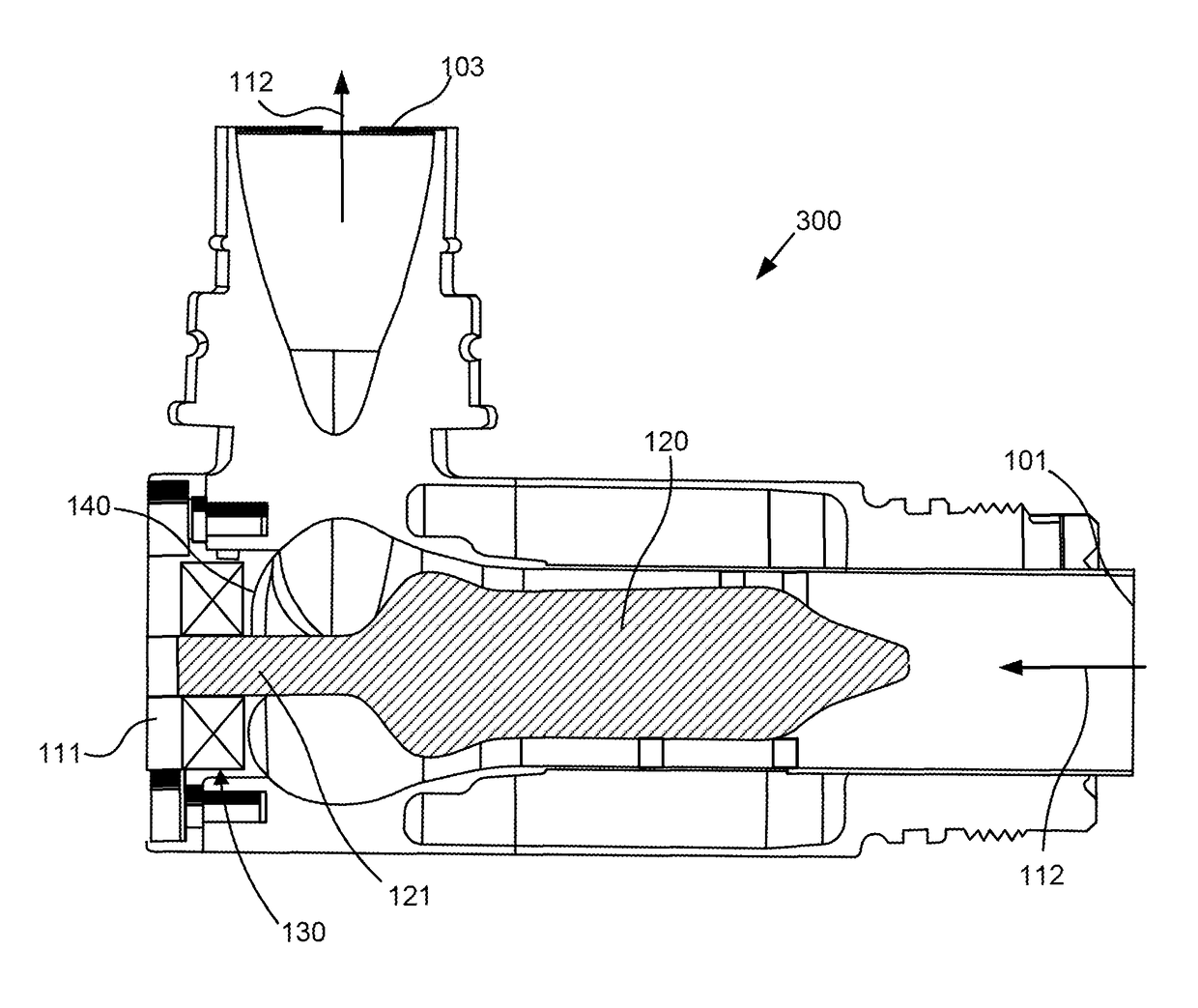
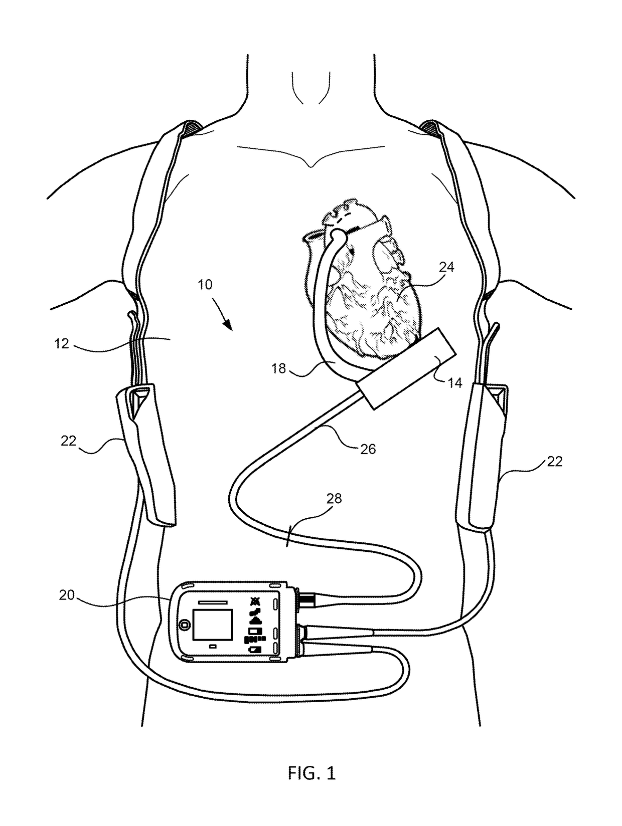
[0028]FIG. 1 is an illustration of a mechanical circulatory support system 10 implanted in a patient's body 12. The mechanical circulatory support system 10 comprises an implantable blood pump 14, outflow cannula 18, system controller 20, and power sources 22. The implantable blood pump 14 may comprise a VAD that is attached to an apex of the left ventricle, as illustrated, or the right ventricle, or both ventricles of the heart 24. The VAD is typically an axial flow pump as described in further detail herein that is capable of pumping the entire output delivered to the left ventricle from the pulmonary circulation (i.e., up to 10 liters per minute). Related blood pumps applicable to the present invention are described in greater detail below and in U.S. Pat. Nos. 5,695,471, 6,071,093, 6,116,862, 6,186,665, 6,234,772, 6,264,635, 6,688,861, 7,699,586, 7,976,271, 7,997,854, 8,007,254, 8,152,493, 8,652,024, and 8,668,473 and U.S. Patent Publication Nos. 2007 / 0078293, 2008 / 0021394, 2009...


PUM


Abstract

Blood pump devices having improved rotor design are provided herein. Such blood pump devices include rotors having cantilevered support through a sealed mechanical bearing disposed outside a blood flow path of the device so as to avoid thrombus formation caused by blood contact with the bearing. The bearing means can be rotatably coupled with a proximal portion of the rotor shaft extending outside the fluid path, while a stator drives rotation of the rotor shaft so that one or more rotor blades on a distal portion of the rotor force blood flow through the device. The bearing means may include one or more radial bearings on a proximal portion of the rotor shaft that are isolated from the blood flow path by one or more rotary seals.

Description

CROSS-REFERENCES TO RELATED APPLICATIONS[0001]This application claims the benefit of U.S. Provisional Application No. 62 / 195,258, filed on Jul. 21, 2015, and entitled “CANTILEVERED ROTOR PUMP AND METHODS FOR AXIAL FLOW BLOOD PUMPING,” the entirety of which is hereby incorporated herein by reference.[0002]This application relates generally to U.S. application Ser. No. 14 / 489,041 entitled “Pump and Method for Mixed Flow Blood Pumping” filed Sep. 17, 2014; U.S. application Ser. No. 13 / 273,185 entitled “Pumping Blood” filed Oct. 13, 2011; each of which is incorporated herein by reference in its entirety for all purposes.BACKGROUND[0003]This application relates generally to mechanical circulatory support systems, and more specifically relates to improved rotor designs in axial flow blood pumps.[0004]Ventricular assist devices, known as VADs, are implantable blood pumps used for both short-term (i.e., days, months) and long-term applications (i.e., years or a lifetime) where a patient's h...

Claims


Application Information

Patent Timeline
Patent Type & Authority Patents(United States)
IPC IPC(8): A61M1/12A61M1/10A61M60/178A61M60/242A61M60/422A61M60/508A61M60/806A61M60/825A61M60/88
CPCA61M1/1013A61M1/1036A61M1/101A61M1/122A61M1/1025A61M1/1031A61M1/1012A61M60/422A61M60/148A61M60/88A61M60/178A61M60/508A61M60/806A61M60/242A61M60/825A61M60/419
Inventor HODGES, WILLIAM V.
Owner TC1 LLC
Why Eureka
Try Eureka