
Method and system for analyzing gas leak based on machine learning

a technology of machine learning and gas leak analysis, applied in the field of gas concentration distribution measurement, can solve the problems of posing fire and explosion hazards, important natural gas or other gas leaks, and extremely dangerous gas leaks

Active Publication Date: 2018-07-24
XEROX CORP
View PDF4 Cites 27 Cited by
  • Summary
  • Abstract
  • Description
  • Claims
  • Application Information

AI Technical Summary

Benefits of technology

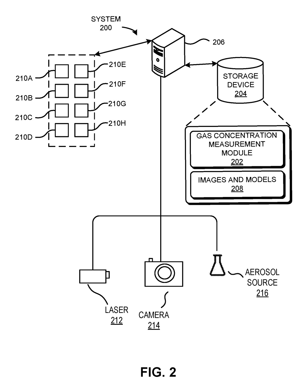
The present invention provides a system and method for measuring the concentration distribution of gas species in an aerosol. The system uses a laser source to illuminate the gas aerosol and a camera to capture images of reflections from the laser sheet. The system analyzes the images to quantify the concentration distribution of the gas aerosol. The system can estimate the location of a gas source based on this information. The system can also select the most suitable location for measuring the gas aerosol based on the characteristics of the wind tunnel or wind turbulence. The system can use multiple laser sheets at different heights and orientations to capture more reflections and improve the accuracy of the concentration distribution measurement. The system can also correct for camera perspective transformation, calibrate image spatial scale, remove artifacts, and isolate the gas plume within the image. The technical effects of the invention include improved accuracy and efficiency in measuring gas concentration distribution in aerosols.

Problems solved by technology

Natural gas or other gas leaks are an important economic and environmental problem.
Gas leaks are extremely dangerous, posing fire and explosion hazards, and in some cases may necessitate emergency responses.
Natural gas is also a very powerful greenhouse gas, therefore gas leaks significantly contribute to greenhouse gas emission.
Moreover, leaks can cause harm to flora and fauna.
But unfortunately, turbulent and chaotic effects, which are neglected by such models, are important for the detailed study of gas and aerosol dispersion in wind.
Specifically, because gas leaks usually originate from well-pads or other equipment near ground level, ground roughness, bluff bodies, etc., can contribute to turbulent flow conditions.
Therefore, Gaussian techniques are limited to leak resolution over scales of at least hundreds of meters—i.e., these techniques are valid in the “far field,” many characteristic lengths, or dimensions of surrounding bluff bodies, from the leak source.
Such large-scale location of leaks is valuable to determine whether a particular oil / gas site is emitting pollution, yet Gaussian methods are incapable of singling out a specific well-pad component, or set of components, as the likely source of a leak.
Thus from an operator's perspective, systems measuring from a distance using inverted Gaussian dispersion models fail to provide relevant intelligence for locating and fixing leak sources.
But sufficiently accurate forward simulation of realistic environmental conditions is highly nonlinear, and is a computationally and theoretically intensive task.
When modeling the time-dependent concentration of a diffusive species in a turbulent flow field, these steady-state models are not applicable.
On the other hand, non-steady computational models (such as Large Eddy Simulation, Detached Eddy Simulation, Direct Numerical Simulation, etc.), are very resource-intensive.
This challenge may be compounded by the fact that turbulent and chaotic flow conditions are particularly sensitive to numerical error, and therefore to the mesh resolution.
Even with adaptive or fractal grids, such a task would currently require supercomputer-level computing power and a significant amount of computing time.

Method used


Image

  • Method and system for analyzing gas leak based on machine learning
  • Method and system for analyzing gas leak based on machine learning
  • Method and system for analyzing gas leak based on machine learning

Examples


Embodiment Construction

[0028]The following description is presented to enable any person skilled in the art to make and use the embodiments, and is provided in the context of a particular application and its requirements. Various modifications to the disclosed embodiments will be readily apparent to those skilled in the art, and the general principles defined herein may be applied to other embodiments and applications without departing from the spirit and scope of the present disclosure. Thus, the present invention is not limited to the embodiments shown, but is to be accorded the widest scope consistent with the principles and features disclosed herein.

Overview

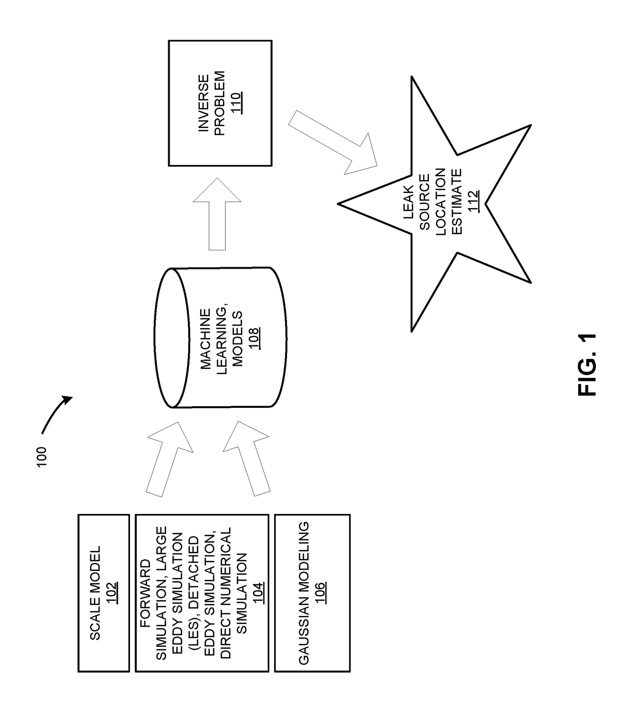
[0029]Embodiments of the present invention solve the problem of estimating a location of a gas leak precisely, by providing forward gas concentration data from an analog or physical scale model including a gas source. The system can use image processing to determine and analyze the gas concentration from images of the scale model, even without carr...


PUM


Abstract

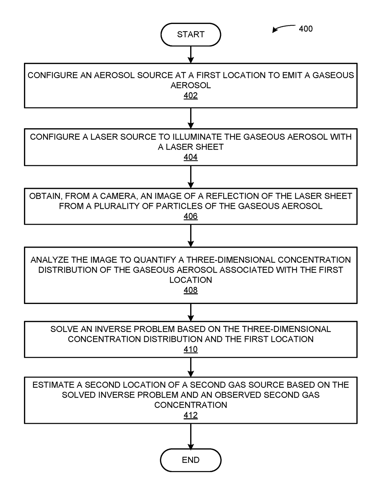
Embodiments of the present invention provide a system for estimating a location of a gas leak, based on machine learning from forward gas concentration data provided by an analog or scale model including a gas source. The system improves significantly over previous systems by providing high quality, physically accurate forward modeling data inexpensively. During operation, the system configures an aerosol source at a first location to emit a gaseous aerosol. The system then configures a laser source to illuminate the aerosol with a laser sheet. The system may then obtain an image of a reflection of the laser sheet from the aerosol. The system may then analyze the image to quantify a three-dimensional concentration distribution of the aerosol. The system may then estimate, based on solving an inverse problem and an observed second gas concentration, a second location of a second gas source.

Description

STATEMENT OF GOVERNMENT-FUNDED RESEARCH[0001]This invention was made with U.S. government support under Contract No. DE-AR0000542 awarded by the Advanced Research Projects Agency in the Department of Energy (ARPA-E). The U.S. government has certain rights in this invention.BACKGROUNDField[0002]The present disclosure relates to measuring a gas concentration distribution. More specifically, this disclosure relates to a method and system for estimating a location of a gas leak, based on machine learning from forward data provided by an analog or scale model including a gas source.Related Art[0003]Natural gas or other gas leaks are an important economic and environmental problem. A recent federal study estimated that the financial cost of natural gas lost to leaks, in Massachusetts alone, reached $1.5 billion from 2000 to 2011. Gas leaks are extremely dangerous, posing fire and explosion hazards, and in some cases may necessitate emergency responses. Natural gas is also a very powerful ...

Claims


Application Information

Patent Timeline
Patent Type & Authority Patents(United States)
IPC IPC(8): G06K9/00G01M3/00G01B11/28G06T7/514G06T5/00G06T7/557G06T7/00
CPCG01M3/007G01B11/28G06T7/514G06T5/003G06T7/557G06T7/001G06T2207/10024G06T2207/10004G06T2207/20081G06T2207/30204G01M3/38G06T7/0004G01N21/00
Inventor SMITH, CLINTON J.SAHA, BHASKARBECK, VICTOR A.SCHWARTZ, DAVID E.
Owner XEROX CORP
Learn More