

Method of and apparatus for protecting a switch, such as a MEMS switch, and to a MEMS switch including such a protection apparatus
a protection apparatus and switch technology, applied in the direction of relays, circuit-breaking switch details, emergency protective arrangements for limiting excess voltage/current, etc., can solve the problems of high switching stress, low insertion loss, and large size of the switch, so as to reduce the switching stress
- Summary
- Abstract
- Description
- Claims
- Application Information
AI Technical Summary
Benefits of technology
Problems solved by technology
Method used
Image

Examples
Embodiment Construction
[0004]It would be desirable to facilitate the use of MEMS switches across a greater range of a devices and applications. In order to do this, the potential issues associated with damage during opening and closing of the switch would benefit from being addressed.
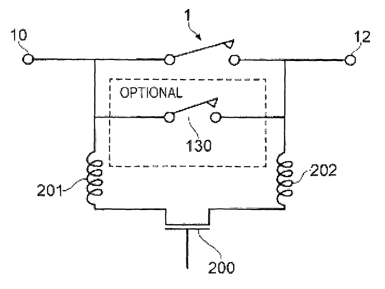
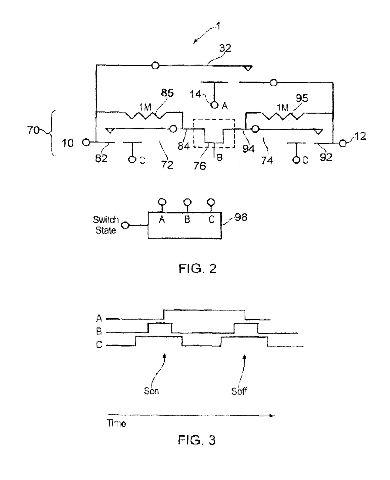
[0005]This disclosure relates to a method of protecting a switch. The protection is implemented during the opening and closing operations of the switch. The protection comprises providing a controllable shunt path in parallel with the switch. The shunt path can be operated to provide a current flow path in parallel with the switch during the opening and closing operations of the switch. Advantageously the shunt path comprises at least one solid state switch, such as a transistor, in series with at least one mechanical switch.
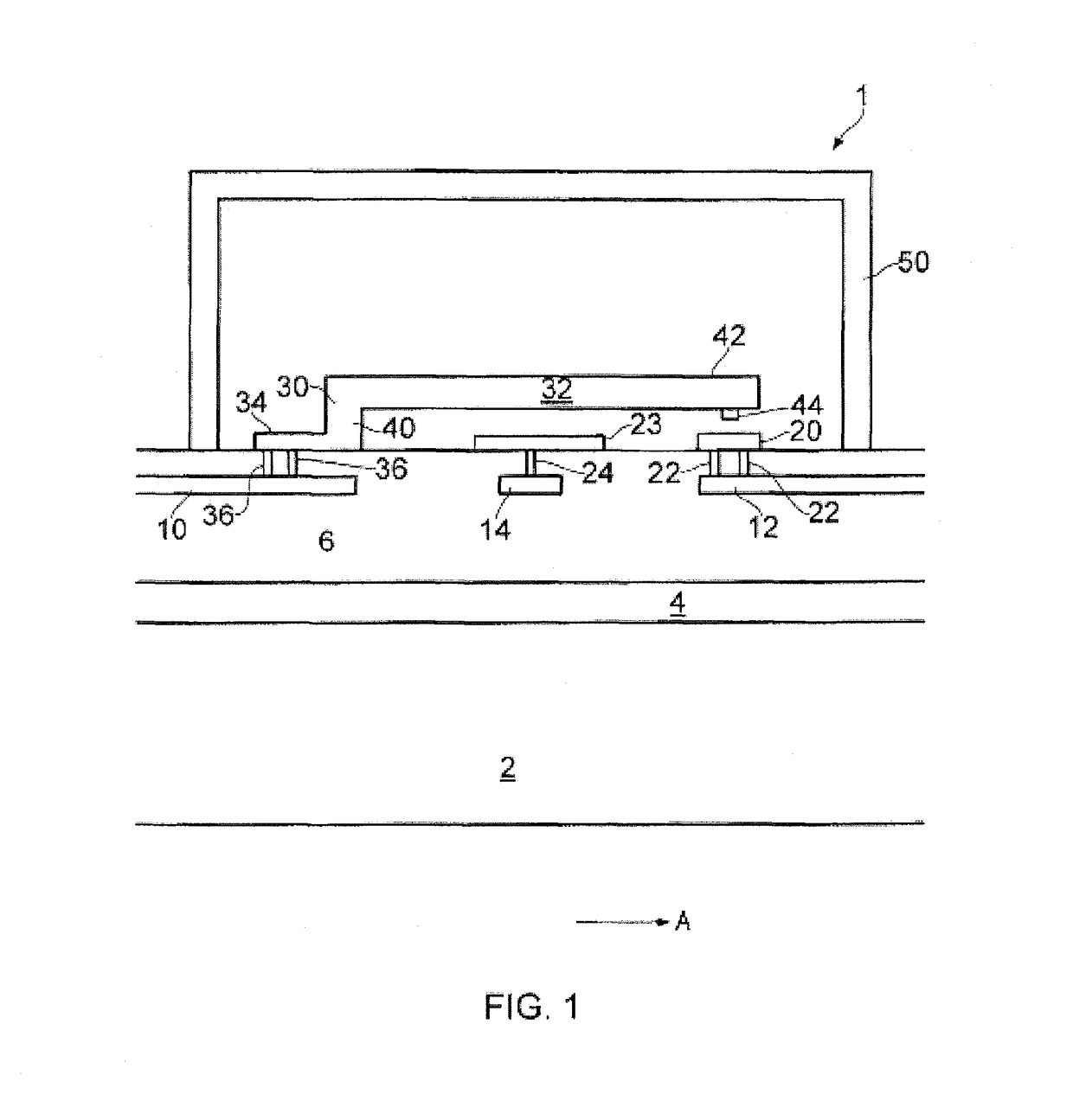
[0006]Preferably the switch is a MEMS switch. The MEMS switch may be provided within an integrated circuit package. Advantageously the at least one mechanical switch is a further MEMS switch. As a result ...
PUM
 Abstract
Description
Claims
Application Information