Low magnetic flux density interface layer for spin torque oscillator

a technology oscillator, which is applied in the field can solve the problems of limiting the effectiveness of magnetic recording heads, unable to achieve a recording field sufficient to effectively, and it is difficult to manufacture them to achieve high spin torque efficiency, etc., and achieves the effect of low magnetic flux density

Active Publication Date: 2018-07-31
WESTERN DIGITAL TECH INC
View PDF22 Cites 30 Cited by
  • Summary
  • Abstract
  • Description
  • Claims
  • Application Information

AI Technical Summary

Benefits of technology

[0005]To address these issues, a magnetic field-assisted magnetic recording (MAMR) head is provided, which includes a recording main pole, a seed layer, and a spin torque oscillator (STO) positioned over the main pole, in this order, in a stacking direction from a leading side to a trailing side of the recording head. The STO comprises a spin polarized layer (SPL), an interlayer with fcc structure, and a field generating layer (FGL), in this order in the stacking direction. The FGL comprises a low magnetic flux density interface (LMFDI) layer with bcc structure that directly contacts the interlayer.
[0006]This Summary is provided to introduce a selection of concepts in a simplified form that are further described below in the Detailed Description. This Summary is not intended to identify key features or essential features of the claimed subject matter, nor is it intended to be used to limit the scope of the claimed subject matter. Furthermore, the claimed subject matter is not limited to implementations that solve any or all disadvantages noted in any part of this disclosure.

Problems solved by technology

One challenge in narrowing the width and pitch of write tracks is decreasing a surface area of a main pole of the magnetic recording head at an air bearing surface of the recording media.
Specifically, as the main pole becomes smaller, the recording field becomes smaller as well, limiting the effectiveness of the magnetic recording head, and at some degree of miniaturization, with prior technology it is no longer possible to achieve a recording field sufficient to effectively record magnetic information into the media with such a conventional recording head.
One challenge with spin torque oscillators is that it is difficult to manufacture them to have a high spin torque efficiency.
One factor that can negatively affect spin torque efficiency is defects in the crystal structure of the Heusler alloy in the spin polarized layer (SPL) and / or field generating layer (FGL) of the STO, especially when crystallizing the Heusler alloy in a Heusler layer above an interlayer with fcc structure.
Although the thick interface CoFe layer promotes proper crystalline growth for the Heusler layer, the high magnetic flux density of the interface CoFe layer also compromises spin torque efficiency.

Method used


Image

  • Low magnetic flux density interface layer for spin torque oscillator
  • Low magnetic flux density interface layer for spin torque oscillator
  • Low magnetic flux density interface layer for spin torque oscillator

Examples


Embodiment Construction

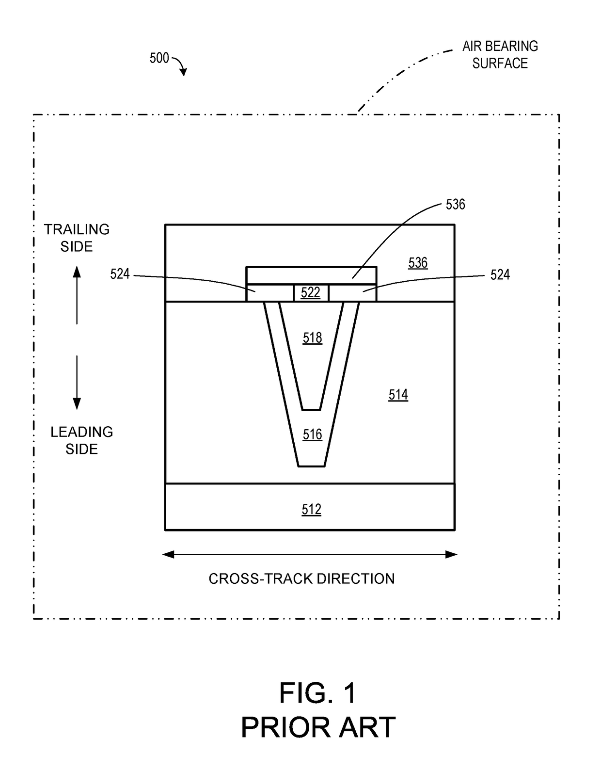
[0017]Referring to FIG. 1, a plan view of an air bearing surface (ABS) of a conventional MAMR magnetic recording head 500 is shown. The MAMR magnetic recording head 500 comprises a main pole 518 adapted for producing a writing magnetic field, a spin torque oscillator (STO) 522 that is positioned on the main pole 518, a trailing gap 524 positioned on the sides of the STO 522, a trailing shield 536 positioned on the trailing gap 524 and the STO 522 on a trailing side of the main pole 518, a side shield 514 positioned on at least on side of the main pole 518 in a cross-track direction and set on a substrate 512, and a side gap 516 positioned between the side shield 514 and the main pole 518. During manufacturing, the main pole 518 is typically plated on top of the side gap 516 in a trench configuration. The main pole 518 is configured to emit a recording magnetic field for affecting a magnetic medium, the main pole 518 serving as an electrode and having a front portion at the ABS. The ...


PUM

PropertyMeasurementUnit
magnetic flux densityaaaaaaaaaa
thicknessaaaaaaaaaa
magnetizationaaaaaaaaaa

Abstract

A magnetic field-assisted magnetic recording (MAMR) head is provided, which includes a recording main pole, a seed layer, and a spin torque oscillator (STO) positioned over the main pole, in this order, in a stacking direction from a leading side to a trailing side of the recording head. The STO comprises a spin polarized layer (SPL), an interlayer with fcc structure, and a field generating layer (FGL), in this order in the stacking direction. The FGL comprises a low magnetic flux density interface (LMFDI) layer with bcc structure that directly contacts the interlayer.

Description

CROSS-REFERENCE TO RELATED APPLICATIONS[0001]This application is a continuation of and claims the benefit of priority to commonly-owned pending U.S. patent application Ser. No. 15 / 195,876 filed on Jun. 28, 2016, the entire content of which is incorporated by reference for all purposes as if fully set forth herein.BACKGROUND[0002]The present invention relates to a magnetic recording head having a function for inducing magnetization reversal by applying a high-frequency magnetic field to a magnetic recording medium, and to a magnetic recording and reproduction device.[0003]In order to achieve higher recording densities for a magnetic recording head mounted in a hard disk device, it is necessary to narrow the width and pitch of write tracks, and thus correspondingly narrow the magnetically recorded bits encoded in each write track. One challenge in narrowing the width and pitch of write tracks is decreasing a surface area of a main pole of the magnetic recording head at an air bearing ...

Claims


Application Information

Patent Timeline
Patent Type & Authority Patents(United States)
IPC IPC(8): G11B5/31G11B5/147G11B5/00
CPCG11B5/3153G11B5/147G11B2005/0024G11B5/235G11B5/3146
Inventor OKAMURA, SUSUMUSATO, MASASHIGENAGASAKA, KEIICHISATO, YO
Owner WESTERN DIGITAL TECH INC
Why Eureka
Try Eureka