Apparatus and method for forming interconnection lines having variable pitch and variable widths

a technology of interconnection lines and equipment, which is applied in the direction of electrical equipment, semiconductor devices, semiconductor/solid-state device details, etc., can solve the problems of time delayed shorting between the lines, difficult to achieve the type of variability in saqp process, and difficult to achieve in saqp process. , to achieve the effect of accurate control and variable width of metal lines

Active Publication Date: 2018-08-07
GLOBALFOUNDRIES US INC
View PDF59 Cites 8 Cited by
  • Summary
  • Abstract
  • Description
  • Claims
  • Application Information

AI Technical Summary

Benefits of technology

[0009]The present invention offers advantages and alternatives over the prior art by providing an apparatus, and method of making the same, of a cell of metal lines for an interconnect system of a semiconductor structure. The metal lines are separated by spacers that are not subject to lithographic variation and, therefore, can be very accurately controlled even with a minimum line pitches of 36 nm or less. Additionally, the widths of the metal lines are variable.

Problems solved by technology

Problematically, however, the theoretical minimum regular pitch (i.e., the minimum distance between repetitive features in a semiconductor device structure) for a SAQP process is about 20 nanometers (nm) using conventional lithographic techniques.
This kind of variability in both pitch and line width is very difficult to achieve with a conventional SAQP process.
This type of variability is difficult to achieve in an SAQP process.
Moreover, other prior art processes that have more flexibility than the SAQP process, such as litho-etch litho-etch (LELE), are subject to lithographic variation problems that make them unreliable at small pitches, such as pitches below 36 nm.
Additionally, if the spaces between metal lines in a cell of a semiconductor interconnect system become too narrow due to, for example, such lithographic variability, those unacceptably small spaces can lead to time delayed shorting between the lines.
Next generation lithographic techniques, such as extreme ultraviolet lithography (EUV), may potentially reduce such conventional lithographic variability.
However, such technologies must overcome development problems that currently limit their resolution.
For example, it is currently recognized that EUV cannot practically realize a 40 nm pitch or less, due to stochastic effects in resist exposure.

Method used


Image

  • Apparatus and method for forming interconnection lines having variable pitch and variable widths
  • Apparatus and method for forming interconnection lines having variable pitch and variable widths
  • Apparatus and method for forming interconnection lines having variable pitch and variable widths

Examples


Embodiment Construction

[0044]Certain exemplary embodiments will now be described to provide an overall understanding of the principles of the structure, function, manufacture, and use of the methods, systems, and devices disclosed herein. One or more examples of these embodiments are illustrated in the accompanying drawings. Those skilled in the art will understand that the methods, systems, and devices specifically described herein and illustrated in the accompanying drawings are non-limiting exemplary embodiments and that the scope of the present invention is defined solely by the claims. The features illustrated or described in connection with one exemplary embodiment may be combined with the features of other embodiments. Such modifications and variations are intended to be included within the scope of the present invention.

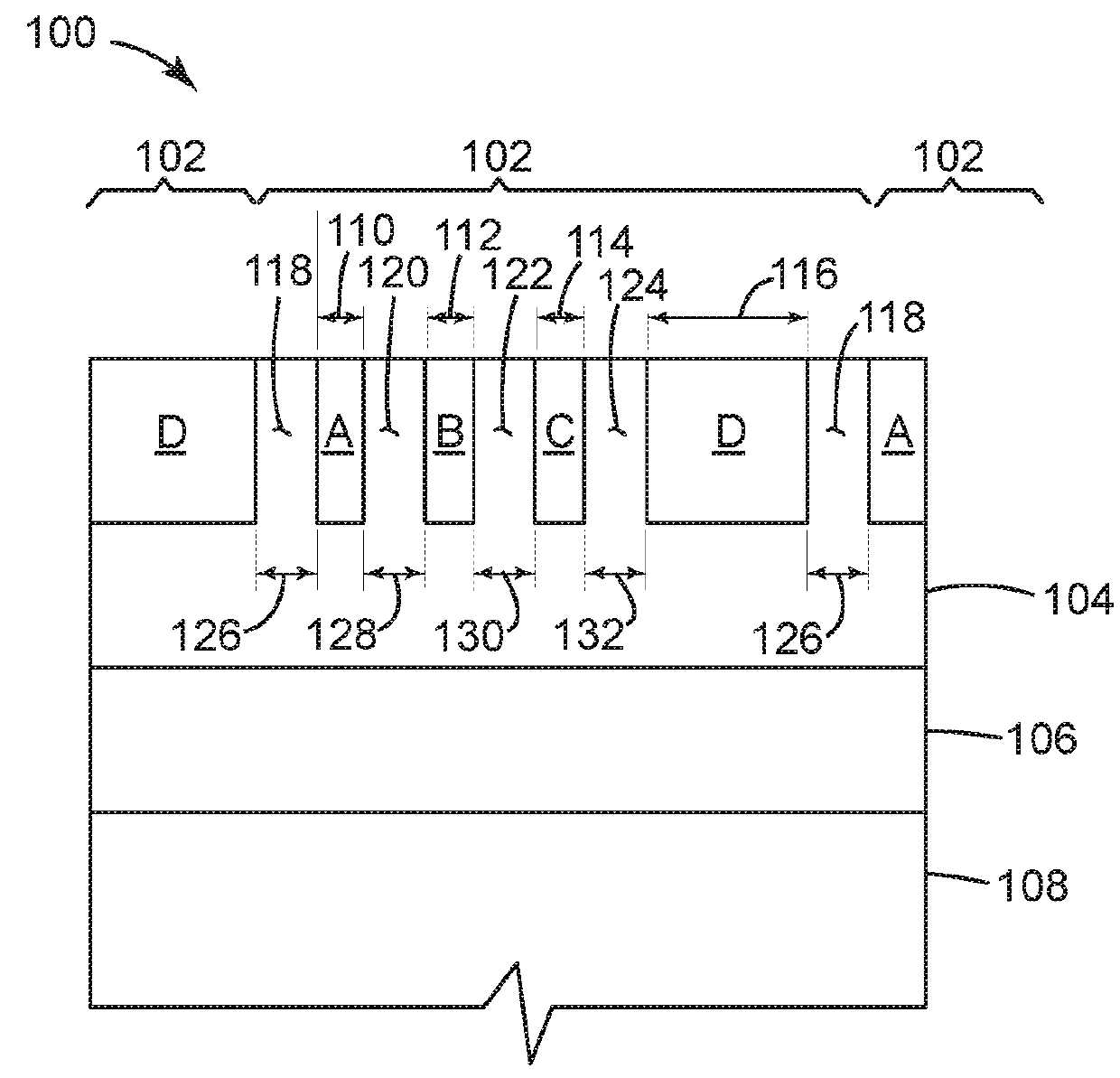
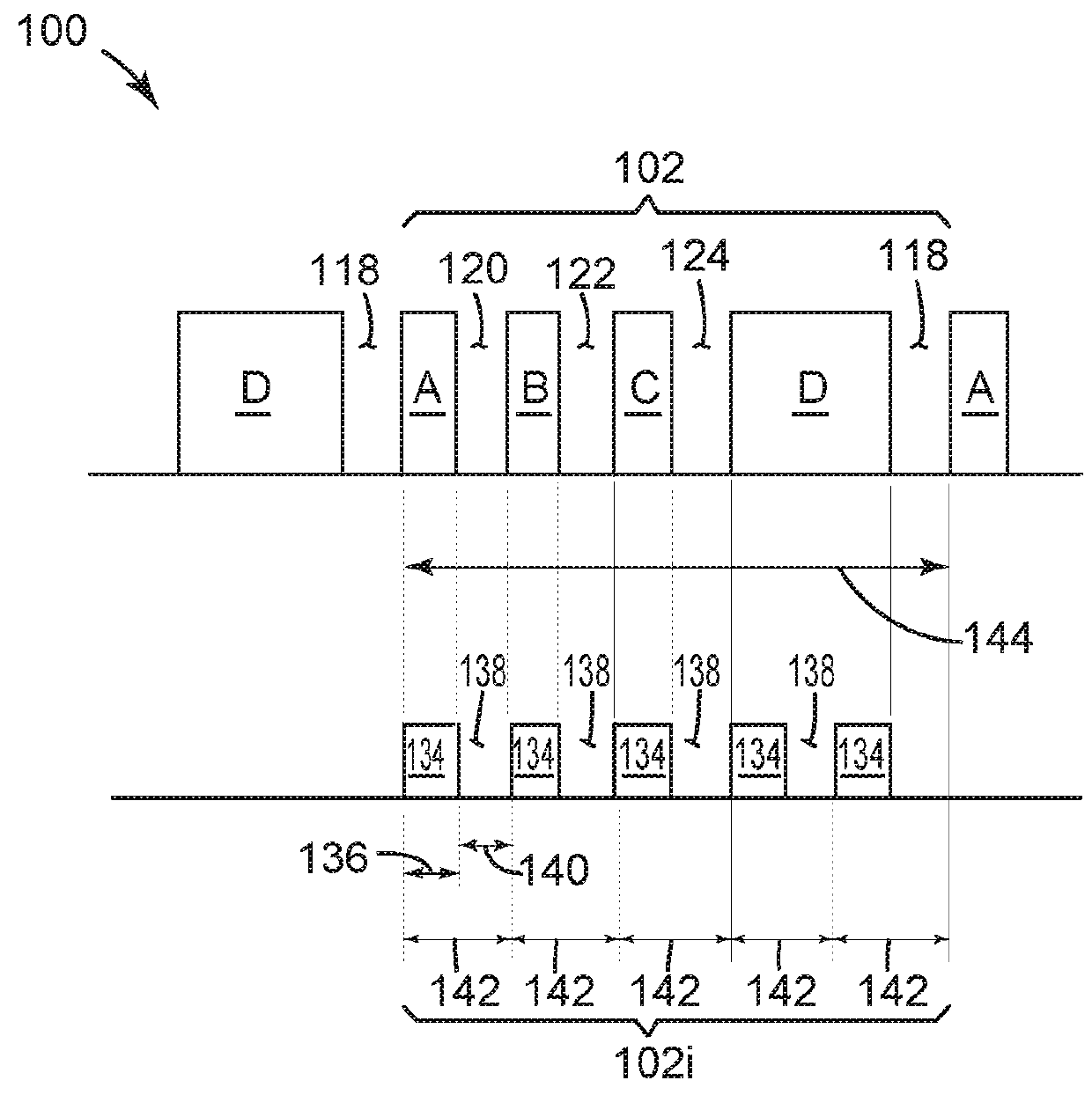
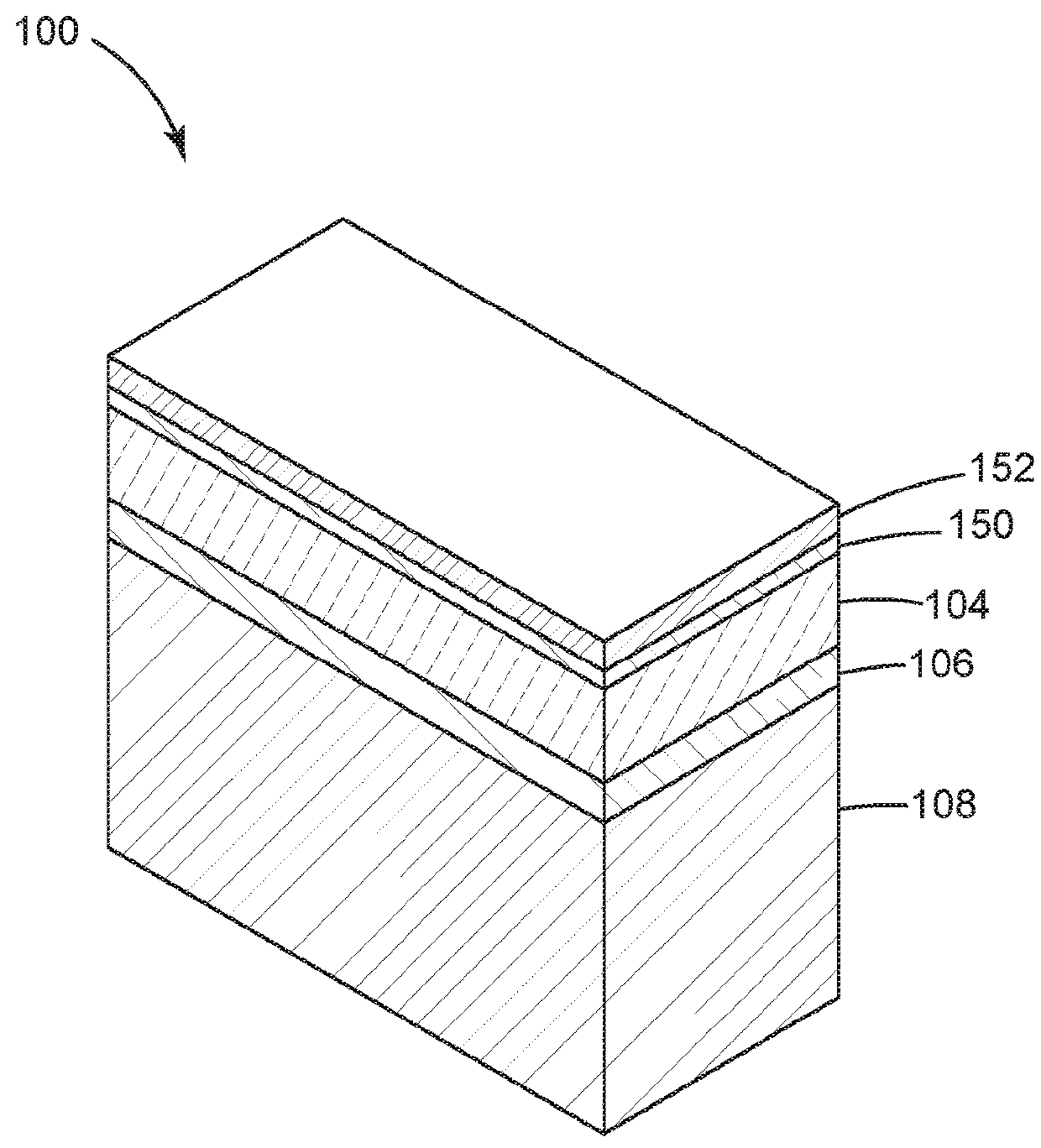
[0045]FIGS. 1-30B illustrate various exemplary embodiments of an apparatus, and method of making the same, of cells of an interconnect system for a semiconductor structure, wherein...


PUM


Abstract

A semiconductor cell includes a dielectric layer. An array of at least four parallel metal lines is disposed within the dielectric layer, the metal lines having line widths that are substantially equal to or greater than a predetermined minimum line width. Line spacers are disposed between the metal lines, the line spacers having line spacer widths that are substantially equal to or greater than a predetermined minimum line spacer width. An overall cell height of the cell is substantially equal to an integer multiple of a plurality of cell tracks, each cell track being a minimum pitch of the cell. The minimum pitch being defined by the minimum line width plus the minimum line spacer width. The minimum pitch is equal to or less than 36 nm. Not all of the line widths are substantially equal and every other line spacer width is substantially equal.

Description

TECHNICAL FIELD[0001]The present invention relates to semiconductor devices and methods of fabricating the same. More specifically, the invention relates to a method and apparatus of forming back end of the line (BEOL) interconnection metal lines having variable pitch and variable line widths.BACKGROUND[0002]Technologies for fabricating semiconductor devices, such as transistors, capacitors and the like, for ultra-high density integrated circuits have been developed which extend patterning resolution beyond that of conventional lithography (which is typically limited to about 80 nm pitch). Self-aligned multiple patterning is one such class of high resolution patterning technologies. The current state of the art multiple patterning technology contemplated for commercial production is a method known as Self-Aligned Quadruple Patterning (SAQP), which is an extrapolation of the more commonly commercially used Self-Aligned Double Patterning (SADP) technique. Problematically, however, the...

Claims


Application Information

Patent Timeline
Patent Type & Authority Patents(United States)
IPC IPC(8): H01L23/528H01L23/532H01L21/302H01L21/308H01L21/768H01L21/033H01L23/522
CPCH01L23/53209H01L21/76877H01L23/53242H01L23/53257H01L21/76816H01L21/302H01L21/308H01L23/53228H01L23/528H01L23/5226H01L23/5286H01L21/0337H01L21/31144
Inventor BOUCHE, GUILLAUMELICAUSI, NICHOLAS VINCENT
Owner GLOBALFOUNDRIES US INC
Why Eureka
Try Eureka