Check patentability & draft patents in minutes with Patsnap Eureka AI!

Automated luminaire location identification and group assignment using light based communication for commissioning a lighting control system

a technology of automatic luminaire location identification and group assignment, which is applied in the direction of electroluminescent light sources, electrical light circuit arrangements, electrical apparatus, etc., can solve the problems of large time and labor expenditure on luminaire/networked device identification, loss/damage of physical media such as installation drawings (with ids attached), and achieve cost-effective effects of reducing manual efforts

Active Publication Date: 2018-08-07
GOOEE
View PDF12 Cites 11 Cited by
  • Summary
  • Abstract
  • Description
  • Claims
  • Application Information

AI Technical Summary

Benefits of technology

The patent describes a system and method for automatically identifying and assigning luminaires in a lighting control system using light based communication. The system includes a sensor subsystem with embedded light based communication techniques, a gateway, network devices, a cloud server, and network gateways. The sensor subsystem senses and captures environmental data and human activities in real-time. The system can control the dimming levels of the luminaires and power to the luminaire using a dimming control protocol. The system can also communicate with other devices in the lighting control system using light based communication. The technical effects of this patent include improved automation and efficiency in identifying and commissioning lighting control systems.

Problems solved by technology

Further, the VLC receiver only receives signals if they reside in the same room as the transmitter and receivers outside the room of the VLC source will not be able to receive the signals, contrary to an RF signal which may be received by any receiver configured to the appropriate frequency and within range of the RF transmission.
A specific location inside a room with no GPS access is required as the GPS cannot be used for accuracy reasons and thus a lighting device does not know its own location.
As the size of a single lighting control network grows beyond that of a single zone of a floor, to the whole floor, the whole building and areas beyond; the time and labor expended on luminaire / networked device identification will likely be quite extensive.
If during the physical installation of an intelligent lighting control system, all information regarding addresses and locations has been accurately mapped and added directly to a commissioning application / tool or drawing, the issue of post-installation identification may not generally present a major problem; however from experience this is not always accurately carried out by electricians / installers and physical media such as installation drawings (with IDs attached) can be lost / damaged.
Further, when changing devices, or replacing the gateway or the luminaire, the installer needs to follow a long manual procedure that is open to errors.

Method used


Image

  • Automated luminaire location identification and group assignment using light based communication for commissioning a lighting control system
  • Automated luminaire location identification and group assignment using light based communication for commissioning a lighting control system
  • Automated luminaire location identification and group assignment using light based communication for commissioning a lighting control system

Examples


embodiment 500

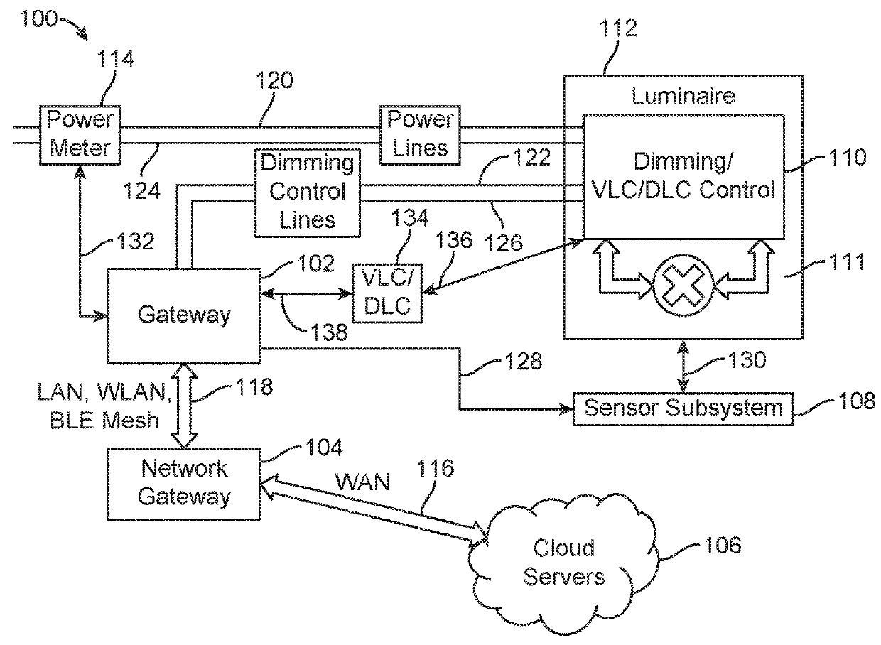
[0071]FIG. 5 illustrates an embodiment 500 of the power meter 114, which may be used in the system 100. Any known ‘power meter device consistent with this disclosure may be used. According to an aspect, the power meter 114 may be wirelessly or physically connected with and / or have physical connectivity within the USLG 102 (see, for example, FIG. 1). In one embodiment, the list of information that is communicated by the power meter 114 via the UART includes: RMS Voltage, Voltage THD, RMS current, Current THD, Active Power, Reactive power, Apparent power, Power factor, and Frequency. Various mixed signal microcontrollers 204, such as those sold by Texas Instruments under the Manufacturer's Code “MSP43012041” may be used by the system 100 and are able to communicate with the power meter 114.

[0072]In general, aspects of the present disclosure describe a method for automatic luminaire location identification and group assignment using light based communication / visual light communication ...

embodiment 700

[0076]FIG. 7 illustrates an embodiment 700 of a protocol list data structure 710 for the gateway 102. The data structure 710 may be designed such that it is easy to traverse the protocol options and pick the correct protocol during the discovery process. The protocol list includes N protocols, were N can be any number. In an embodiment, each protocol (X 702, Y 704, Z 706 . . . W 708) contains directives to the gateway 102 to setup the specific protocol interface (e.g., power level, specific line connections, and other required information as dictated by the protocol standard interface). Further, each protocol may contain a set of directives / actions numbered 1-N. The discovery process may use these directives to take actions like sending a message or changing the voltage level over the dimming control lines. According to an aspect, each action in the list is associated with a list of sensor measurement ranges, one per sensor and per power meter. These measurement ranges may be compar...

embodiment 800

[0077]FIG. 8 illustrates an embodiment 800 of the protocol discovery process 802. According to an aspect, at step 804, the protocol is determined from a list of protocols, as seen, for instance, in FIG. 7. At step 806, the process may include retrieving / taking / assuming a protocol from the list of protocols, and mark it as the “current protocol”. The current protocol may include a dimming control protocol. At step 808, the system may check if the entire list of protocols is finished. If the list is completed ‘Yes’, then the next step of operation goes to step 810, which may indicate that there has been a failure to identify a protocol. In an embodiment, when a current protocol that has passed all of the verifications correctly is found, proper identification of the protocol and / or the identification process will be successfully achieved. If the list is not finished, ‘No’, then the next step of operation may go to step 812. According to an aspect, at step 812, the system activates the...


PUM


Abstract

Devices, systems, and methods for automatic luminaire location identification and group assignment using light based communication / visual light communication (VLC) / dark light communication (DLC) for commissioning a lighting control. Further, the devices, systems, and methods provide automated luminaire identification and exact luminaire locations where all luminaire devices are located relative to at least one luminaire to create location identification without knowing the group. The disclosed devices, systems, and methods provide enhanced lighting system commissioning, maintenance, and updating.

Description

CROSS REFERENCE TO RELATED APPLICATIONS[0001]This application is a continuation-in-part of U.S. patent application Ser. No. 15 / 643,244 filed Jul. 6, 2017, which claims the benefit of U.S. Provisional Patent Application No. 62 / 492,849 filed May 1, 2017. This application claims the benefit of U.S. Provisional Patent Application No. 62 / 511,300 filed May 25, 2017. The disclosures in each of the applications identified above are incorporated herein by reference in their entireties.FIELD OF THE DISCLOSURE[0002]Devices, systems, and methods for automated luminaire location identification using light are generally described. In particular, systems and methods for automatic luminaire location identification and group assignment using light based communication / visual light communication (VLC) / dark light communication (DLC) for commissioning a lighting control are disclosed.BACKGROUND OF THE DISCLOSURE[0003]In lighting control systems with distributed networked / intelligent lighting devices it ...

Claims


Application Information

Patent Timeline
Patent Type & Authority Patents(United States)
IPC IPC(8): H05B33/08H05B37/02H05B44/00
CPCH05B37/0218H05B37/0272H05B33/0854H05B47/195Y02B20/40H05B45/20H05B45/12H05B47/199H05B47/11
Inventor COOMBES, SIMONSILVERMAN, SHMUEL
Owner GOOEE
Features
  • R&D
  • Intellectual Property
  • Life Sciences
  • Materials
  • Tech Scout
  • Unparalleled Data Quality
  • Higher Quality Content
  • 60% Fewer Hallucinations
Learn More