
Interference cancellation in an FMCW radar

a technology of interference cancellation and radar, applied in the direction of reradiation, measurement devices, instruments, etc., can solve the problems of insufficient distance separation capability, undesired reception of radar signals from other vehicles in specific traffic scenarios, and increased probability that radar sensors will also receive undesired interference signals, etc., to achieve the effect of increasing the number of radar sensors

Active Publication Date: 2018-08-14
ROBERT BOSCH GMBH
View PDF24 Cites 10 Cited by
  • Summary
  • Abstract
  • Description
  • Claims
  • Application Information

AI Technical Summary

Benefits of technology

The invention provides an FMCW radar system and sensor with chirp sequence modulation that can effectively suppress undesired signals from other radar sensors of the same vehicle. This is achieved by using mutually orthogonal code sequences that lead to ideal suppression of interfering radar echoes from signals of the other radar sensor. This reduces mutual interference within a radar system of a vehicle and external interference between radar sensors of two vehicles.

Problems solved by technology

This increases the probability that a radar sensor will also receive an undesired interfering signal from another radar sensor of the same vehicle.
As radar sensors become increasingly widespread in motor vehicles, undesired reception of radar signals from other vehicles can also occur in specific traffic scenarios.
In stop-and-go driving, for example, a rear radar sensor of a preceding vehicle could interfere with a front radar sensor of the vehicle behind.
Due to the available bandwidth this is possible only to a limited extent, however, and results in deficiencies in distance separation capability.

Method used


Image

  • Interference cancellation in an FMCW radar
  • Interference cancellation in an FMCW radar
  • Interference cancellation in an FMCW radar

Examples


Embodiment Construction

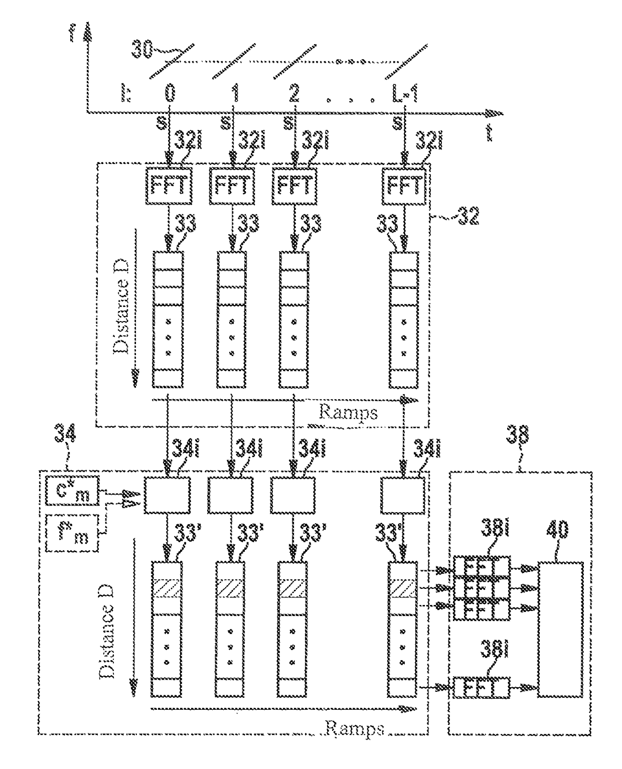
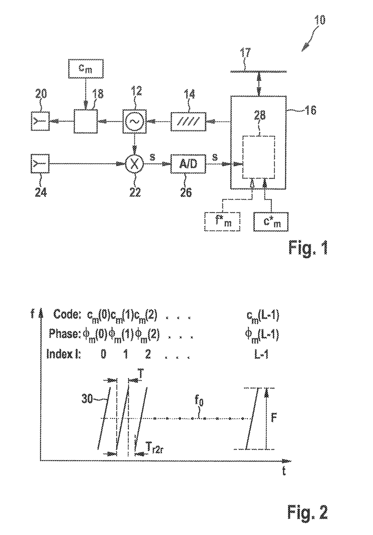
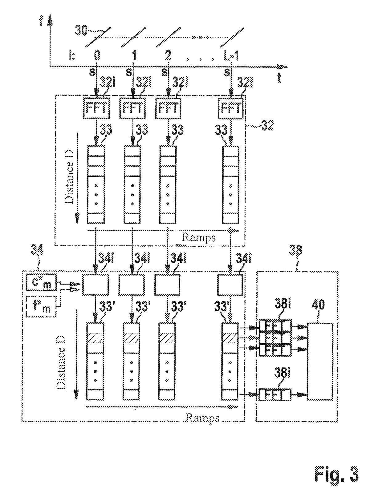
[0036]FMCW radar sensor 10 shown in FIG. 1 is installed in the front of a motor vehicle. It encompasses an oscillator 12 for generating a transmitted signal, a frequency modulation device 14 for controlling the frequency of oscillator 12, and a control and evaluation unit 16 that is connectable to a vehicle bus system 17. An output of oscillator 12 is connected via a controllable phase modulator 18 to a transmitting antenna element 20. An output of oscillator 12 is furthermore connected to a mixer 22. The latter is configured to mix a received signal received by a receiving antenna element 24 with the frequency-modulated signal of oscillator 12 in order to generate a baseband signal s. The baseband signal is sampled and digitized by an analog-digital converter 26. Mixing and digitization are performed while retaining the phase relationships between the received signal and the transmitted signal. Control and evaluation unit 16 controls frequency modulation device 14, and encompasses ...


PUM


Abstract

A radar system for transmitting a FMCW radar sensor signal encompassing a series of frequency modulation ramps and phase-modulated with a first code sequence orthogonal to a respective other code sequence with which a time-synchronized transmitted signal of another FMCW radar sensor is phase-modulated; the radar echoes are phase-demodulated with a code sequence correlating with the first code sequence; and a distance and / or a relative speed of a localized object is identified from a Fourier analysis frequency spectrum, in a first dimension over sampled radar echo values of a frequency modulation ramp, and in a second dimension over the phase-demodulated sequence of radar echoes of the ramps of the transmitted signal; and a vehicle fleet radar system having an FMCW radar sensor in which a code set satisfying a code set orthogonality condition with a code set of a radar sensor of another vehicle is used for phase modulation / demodulation.

Description

FIELD OF THE INVENTION[0001]The present invention relates to the identification of distances and / or relative speeds of objects using an FMCW radar. The invention relates in particular to an FMCW radar sensor, to an FMCW radar system having a first and at least one second radar sensor, and to a radar system for a vehicle fleet encompassing multiple FMCW radar sensors.BACKGROUND INFORMATION[0002]Radar sensors are used in motor vehicles, for example, to measure the distances, relative speeds, and azimuth angles of vehicles or other objects located in the area in front of the own vehicle.[0003]In a frequency-modulated continuous wave (FMCW) radar sensor, the transmission frequency of a continuous radar signal is modulated in the form of ramps. A baseband signal is generated from a received signal by mixing with the transmitted signal, and is then evaluated.[0004]FMCW radar sensors that operate according to the chirp sequence modulation method, in which the transmitted signal encompasses...

Claims


Application Information

Patent Timeline
Patent Type & Authority Patents(United States)
IPC IPC(8): G01S13/34G01S13/38G01S13/536G01S13/58G01S13/87G01S13/93G01S7/02G01S13/32G01S7/35G01S13/931
CPCG01S13/343G01S13/38G01S13/536G01S13/584G01S13/325G01S13/931G01S7/023G01S13/878G01S2007/356G01S2013/9375G01S13/282G01S13/286G01S13/288G01S13/345G01S2013/93271G01S7/356G01S7/0232G01S7/0233G01S7/0234
Inventor VOGT, JINGYINGSCHOOR, MICHAEL
Owner ROBERT BOSCH GMBH
Learn More