
Three-dimensional computer-aided-design system user interface

a computer-aided design and user interface technology, applied in the field of 3d cad systems, can solve the problems of high learning curve, slow usage, and use of mono-functional buttons and fill-in-the-blank fields

Active Publication Date: 2018-08-14
SELKER TED
View PDF13 Cites 68 Cited by
  • Summary
  • Abstract
  • Description
  • Claims
  • Application Information

AI Technical Summary

Benefits of technology

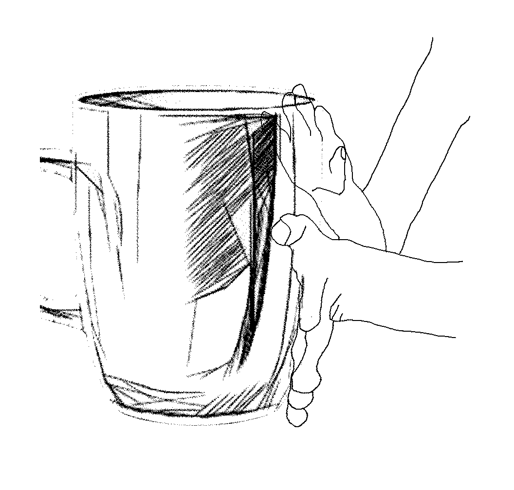
[0011]With respect to a 3D CAD system UI, gestures and poses such as exemplified above are intuitive analogous actions on an object. By using a person's extensive natural, complex anatomy, and their extensive skill set using their hands, both learning the UI and using the UI are made more efficient, including increased productivity, less user frustration and the many other benefits of an improved UI.
[0052]One embodiment lets users select their own mapping. For example, a user may type a known key sequence or perform a mouse-based operation first, then indicate which one or more gestures or poses should map to this operation. In this way, users who have already learned one UI, such as one that uses a keyboard and mouse, can gracefully transition to the more efficient UI of embodiments of this invention. A variation on this embodiment shows, on a screen, a set of recommended gestures or postures in response to a user provided keyboard or mouse sequence. The user may then choose one of the suggested. This option provides more consistency of the UI mapping from one user to the next, and likely provides a more cohesive and consistent mapping set.

Problems solved by technology

A weakness of prior art is the use of mono-functional buttons and fill-in-the-blank fields.
Thus, they suffer both a very high learning curve and slow usage.

Method used


Image

  • Three-dimensional computer-aided-design system user interface
  • Three-dimensional computer-aided-design system user interface
  • Three-dimensional computer-aided-design system user interface

Examples


Embodiment Construction

[0071]The 3D CAD system environment includes what is sometimes called a Virtual Reality (VR) development environment.

[0072]Methodology for implementing maps from hand gestures and poses to 3D CAD system actions or commands is not hard. The most current 3D CAD system commands are listed starting with the most common. Experienced 3D CAD system users are then asked what hand gestures and poses they think best represent those commands. Consensus or majority choices are then used in an initial mapping.

[0073]Similarly, people experienced in gestures, such as either experienced or new users of American Sign Language (ASL) are asked what they think the 500 most common words and letters should do in a 3D CAD system. Consensus or majority choices are then also used in an initial mapping.

[0074]In this way, the proposed mapping is approached “from both ends.”

[0075]Beta users then validate and modify this initial mapping. The beta users set should include both experienced and new uses of 3D CAD ...


PUM


Abstract

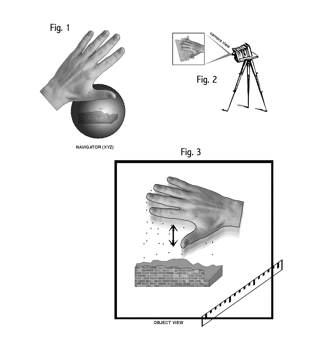
A three-dimensional (3D) computer aided design (CAD) user interface (UI) is described that maps both two-handed and one-handed free hand gestures and poses to map to actions in the 3D CAD UI environment. Free hands may be used to directly both constrain and organically modify an object. Intuitive analogs to physical tools are used, with gradual changes to visibility. Parts are automatically modified to meet object-specific and rule-based constraints. Multiple copies of a physical analog element, with known dimensions, may be continually created by a free hand and automatically assembled into an appropriate, organized and contiguous structure containing integral visible fiducials based on the dimensions of the element. Temporary layers of an object are used to permit organic modifications of portions of an object. Use of a fastener creates and then fastens to a mating part. Visible physical analogs provide perspective. Non-linear magnification permits rapid, wide dynamic range object modification.

Description

FIELD OF THIS INVENTION[0001]The problem to be solved is, “how to make a three-dimensional (3D) computer aided design (CAD) system more effective.” The field is 3D CAD systems. The field is more particularly the user interface (UI) of a 3D CAD system.[0002]A 3D CAD system includes design or viewing capabilities, or both. Prior art in 3D CAD UI includes keyboards, touch pads, touchscreens, mice, trackballs, and tablets. Actions of the 3D CAD system responsive to these sensors include changing the dimensions of an object; changing a viewpoint of the object; moving one portion of an object with respect to another portion of an object; selecting a component from a library; drawing a portion of an object; altering the material or texture of an object; performing administrative functions such as loading, saving, transmitting or printing object data; and the like. By “object,” we mean any part, portion, attribute or entirety of an object or set of associated objects. “Object” may be the tr...

Claims


Application Information

Patent Timeline
Patent Type & Authority Patents(United States)
IPC IPC(8): G06F3/048G06F3/0481G06F3/0484G06F3/01G06F17/50
CPCG06F3/017G06F3/04842G06F3/04815G06F17/50G06F30/00
Inventor SELKER, TEDRUBIN, KIM
Owner SELKER TED
Learn More