Method to remap high priority connection with large congestion window to high latency link to achieve better performance

a high-priority connection and congestion-free technology, applied in the field of data communication networks, to achieve the effect of reducing congestion, reducing latency, and reducing latency

Active Publication Date: 2018-08-14
CITRIX SYST INC
View PDF10 Cites 9 Cited by
  • Summary
  • Abstract
  • Description
  • Claims
  • Application Information

AI Technical Summary

Benefits of technology

[0003]Typical connection prioritization systems direct high priority traffic (e.g., streaming video, or other such traffic) over the highest available quality link of a plurality of links, such as a link with the lowest latency, least congestion, etc. Thus, given two links between computing devices, one with low latency and one with high latency, high priority traffic will be directed via the low latency link. Simultaneously, many congestion avoidance mechanisms, such as the slow start mechanism of the transport control protocol (TCP), restrict the bandwidth useable by a connection during a time period after its establishment. The useable bandwidth rate or congestion window size is increased over several sets of transmissions and acknowledgement responses, and accordingly, is dependent on the connection latency: if the new connection carries lower priority traffic and is correspondingly directed to the high latency link, it will take longer for the connection to increase its congestion window size than if it were to use the low latency link, because each round trip time (RTT) period for the connection will be longer. In some instances in which the low latency link may be rate limited by other devices within the path such that the low latency has less benefit to the high priority traffic, it may be more efficient to switch the links: by allowing the new traffic flow to use the lowest latency link, it may increase its congestion window size and bandwidth throughput faster, while the high priority traffic flow may not be unduly hampered by the low latency link.

Problems solved by technology

Simultaneously, many congestion avoidance mechanisms, such as the slow start mechanism of the transport control protocol (TCP), restrict the bandwidth useable by a connection during a time period after its establishment.

Method used


Image

  • Method to remap high priority connection with large congestion window to high latency link to achieve better performance
  • Method to remap high priority connection with large congestion window to high latency link to achieve better performance
  • Method to remap high priority connection with large congestion window to high latency link to achieve better performance

Examples


Embodiment Construction

[0025]For purposes of reading the description of the various embodiments below, the following descriptions of the sections of the specification and their respective contents may be helpful:

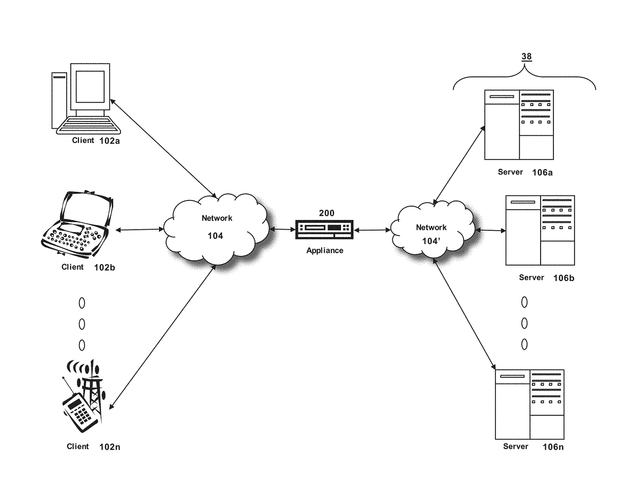
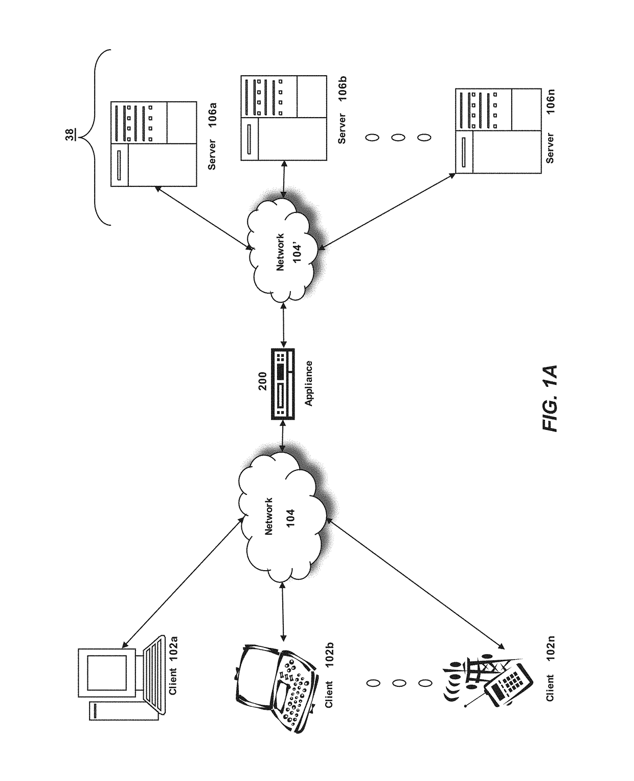
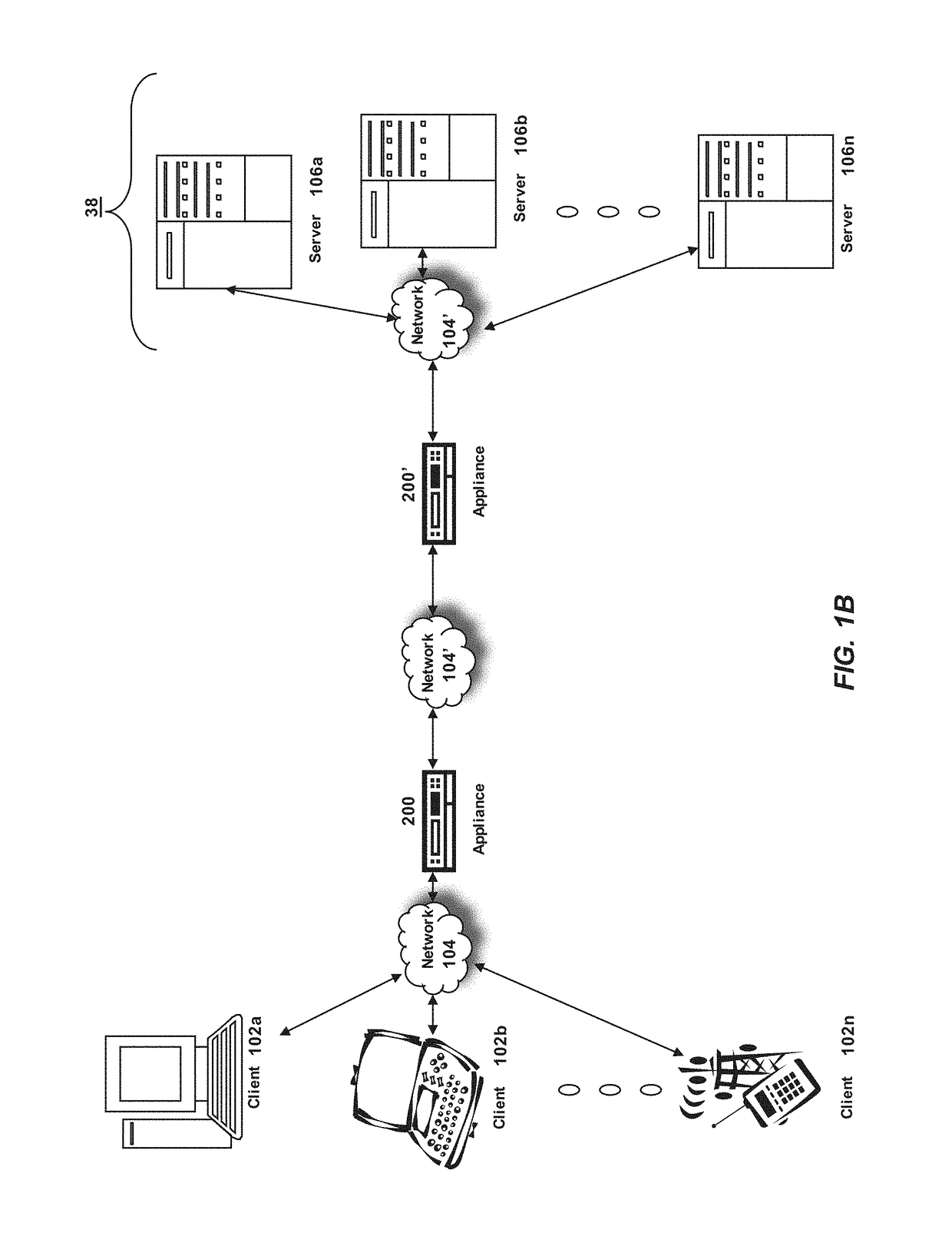
[0026]Section A describes a network environment and computing environment which may be useful for practicing embodiments described herein;

[0027]Section B describes embodiments of systems and methods for delivering a computing environment to a remote user;

[0028]Section C describes embodiments of systems and methods for accelerating communications between a client and a server;

[0029]Section D describes embodiments of systems and methods for virtualizing an application delivery controller;

[0030]Section E describes embodiments of systems and methods for providing a multi-core architecture and environment;

[0031]Section F describes embodiments of systems and methods for providing a clustered appliance architecture environment; and

[0032]Section G describes embodiments of systems and methods for improving...


PUM


Abstract

Described embodiments improve the performance of a computer network via optimization of connection redirection or redistribution based on link characteristics such as latency. In some implementations, a high priority connection may be initially established via an available link having a lowest latency or highest throughput. If the connection is not particularly latency-sensitive, then once the connection has ramped up to a highest throughput (e.g. largest congestion window size, etc.), the connection may be moved to a higher latency link, freeing the lower latency link for new connections to similarly ramp up throughput.

Description

FIELD OF THE DISCLOSURE[0001]The present application generally relates to data communication networks. In particular, the present application relates to systems and methods for improving the performance of computer networks by redistributing high priority connections based on link characteristics.BACKGROUND OF THE DISCLOSURE[0002]Computing devices can be communicatively coupled to one another via a computer network to facilitate the transmission of data (e.g., network packets) between the computing devices. Data can be sent between the networked computing devices according to various protocols, for example using a “layered” networking model such as the open systems interconnection (OSI) model. In some instances, multiple communications links or paths may be utilized between computing devices for transmitting packets. However, due to congestion avoidance mechanisms, some methods of allocating packets among these links or paths may be inefficient or sub-optimal such as prioritizing pa...

Claims


Application Information

Patent Timeline
Patent Type & Authority Patents(United States)
IPC IPC(8): H04L12/26H04L5/00H04L12/803G06F15/16H04L12/801H04L12/851H04L45/28
CPCH04L47/122H04L47/11H04L43/0882H04L43/0864H04L47/24H04L43/0894H04L47/283
Inventor DHANABALAN, PRAVEEN RAJAKALOO, NIKHIL
Owner CITRIX SYST INC
Why Eureka
Try Eureka