System and method for determining the positions of side collision avoidance sensors on a vehicle

a collision avoidance and sensor technology, applied in the field of systems and methods for determining the position of collision avoidance sensors on the sides of vehicles, can solve problems such as the installation of sensors, and achieve the effect of avoiding manufacturing costs and much faster installation of sensors on vehicles

Active Publication Date: 2018-09-04
BENDIX COMML VEHICLE SYST LLC
View PDF18 Cites 10 Cited by
  • Summary
  • Abstract
  • Description
  • Claims
  • Application Information

AI Technical Summary

Benefits of technology

[0009]A system and method for determining the positions of one or more collision avoidance sensors on a vehicle in accordance the present teachings represent an improvement as compared to conventional systems and methods. In particular, the system and method enable a sensor to learn its position on the vehicle as well as its position relative to other sensors based on the speed and direction of movement of objects in the field of view of the sensor relative to the speed and direction of movement of the vehicle. As a result, a single sensor can be used at any position on the vehicle without modifications to other vehicle components. By using a single sensor, manufacturers avoid the costs of manufacturing and programming multiple sensors. Further, installation of the sensors on a vehicle is much quicker and the risk of improper installation of the sensor is significantly reduced.

Problems solved by technology

In addition to the manufacturing costs associated with producing multiple sensors, there is a risk that sensors pre-programmed for one position will be installed in another position on the vehicle during the initial installation of the sensors and / or that an incorrect sensor will be installed when replacing a sensor during a maintenance action.
This method, however, requires the use of different wiring connections and therefore simply transfers the increase in part count to another vehicle component.

Method used


Image

  • System and method for determining the positions of side collision avoidance sensors on a vehicle
  • System and method for determining the positions of side collision avoidance sensors on a vehicle
  • System and method for determining the positions of side collision avoidance sensors on a vehicle

Examples


Embodiment Construction

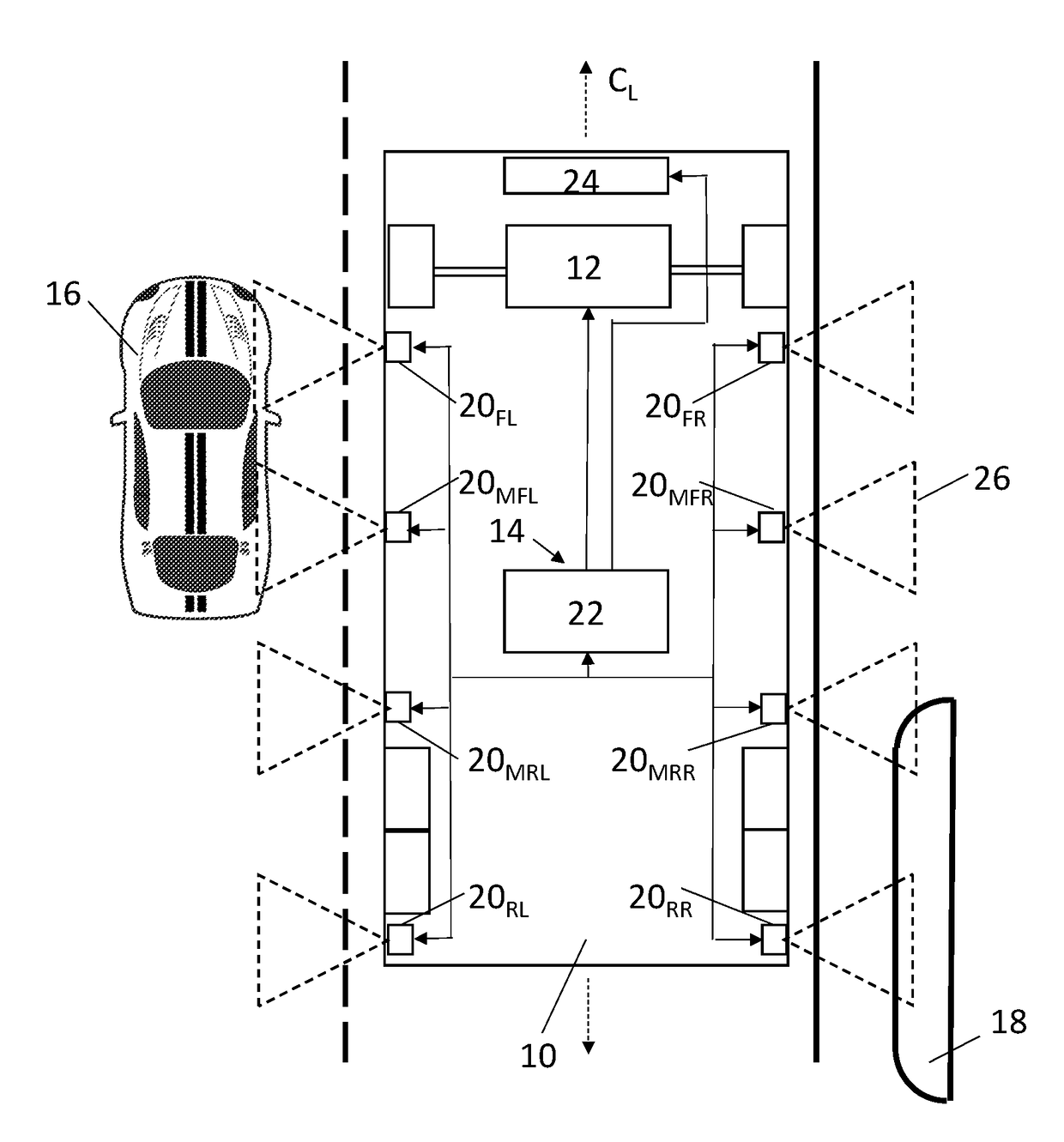
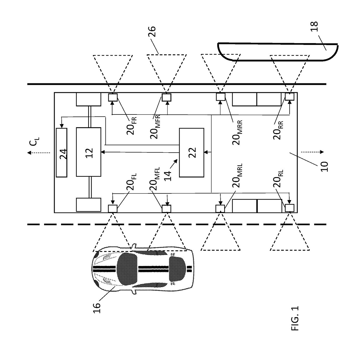
[0013]Referring now to the drawings wherein like reference numerals are used to identify identical components in the various views, FIG. 1 illustrates a vehicle 10. In accordance with certain embodiments, vehicle 10 may include an electric power steering system 12. Vehicle 10 further includes a collision avoidance system in the form or a side object detection system or blind spot monitoring system 14. Vehicle 10 may comprise a heavy commercial vehicle such as a truck, trailers or bus, but it should be understood that systems 12 and 14 may find application on a wide variety of vehicles.

[0014]Electric power steering system 12 provides assistance to the vehicle operator to turn the vehicle wheels and steer vehicle 10. System 12 may also provide the ability for autonomous steering of vehicle 10 without input from the vehicle operator. System 12 may include a conventional electric motor that moves a steering rack connected to wheels on opposite side of the vehicle in response to rotation...


PUM


Abstract

A system and method system for determining the positions of one or more collision avoidance sensors on a vehicle is provided. The system includes one or more sensors disposed on the vehicle and configured to generate electromagnetic waves within corresponding fields of view on a side of the vehicle and to receive reflections of the waves from objects passing through the field of view of each sensor. A controller receives signals generated by the sensors responsive to the reflections and determines, responsive to the signals, relative speeds and relative directions of movement of the objects relative to the vehicle. The controller further determines the position of the sensors on the vehicle responsive to the relative speeds and relative directions of movement. In particular, the controller determines the location of sensors relative to the vehicle centerline and the relative positions and distances between sensors in the direction of vehicle travel.

Description

BACKGROUND OF THE INVENTIONa. Field of the Invention[0001]This invention relates to side collision avoidance systems for vehicles. In particular, the invention relates to a system and method for determining the position of collision avoidance sensors on the sides of a vehicle.b. Background Art[0002]Collision avoidance systems are used in vehicles to prevent collisions between the vehicle and other objects (including other vehicles, pedestrians, and stationary objects such as guardrails) and to reduce the severity of any collisions that do occur. One conventional form of collision avoidance system commonly used on vehicles today is a blind spot monitoring system. Blind spots are areas on or along the roadway that cannot be seen by the vehicle operator using conventional rear view or side view mirrors on the vehicle. Blind spot monitoring systems generate warnings to the vehicle operator when an object is located in a blind spot to discourage the operator from moving the vehicle in a ...

Claims


Application Information

Patent Timeline
Patent Type & Authority Patents(United States)
IPC IPC(8): G01B7/00G01S15/93G08G1/16G01S13/93B60Q9/00G06F13/376G01S17/93G01B11/26G01P21/00G01S7/497G01S7/52G01B7/004B62D41/00B61L23/34B61L15/00B61L23/04G01S13/931G01S15/931G01S17/931
CPCG06F13/376G01S13/931G08G1/167B60Q9/008G01B7/003G01S15/931G01S2013/9385G01S2013/9332G01S2013/9353B61L23/041B61L15/0036B61L23/34B62D41/00G01B7/004G01S7/52004G01S7/4972G01P21/00G01B11/26G01S17/936G01S2013/9371G01S2013/9327G01S2013/93274G01S2013/9315G01S2013/932G01S17/931
Inventor LESHER, MICHAEL K.FRANZ, MARTIN P.
Owner BENDIX COMML VEHICLE SYST LLC
Why Eureka
Try Eureka