Weld electrical and gas connector with sealed gas flow

a gas flow and gas connector technology, applied in the field of welding systems, can solve problems such as complex construction

Active Publication Date: 2018-09-18
ILLINOIS TOOL WORKS INC
View PDF28 Cites 1 Cited by
  • Summary
  • Abstract
  • Description
  • Claims
  • Application Information

AI Technical Summary

Problems solved by technology

Unfortunately, such cable assemblies may include a large number of components and may be complicated to construct.

Method used


Image

  • Weld electrical and gas connector with sealed gas flow
  • Weld electrical and gas connector with sealed gas flow
  • Weld electrical and gas connector with sealed gas flow

Examples


Embodiment Construction

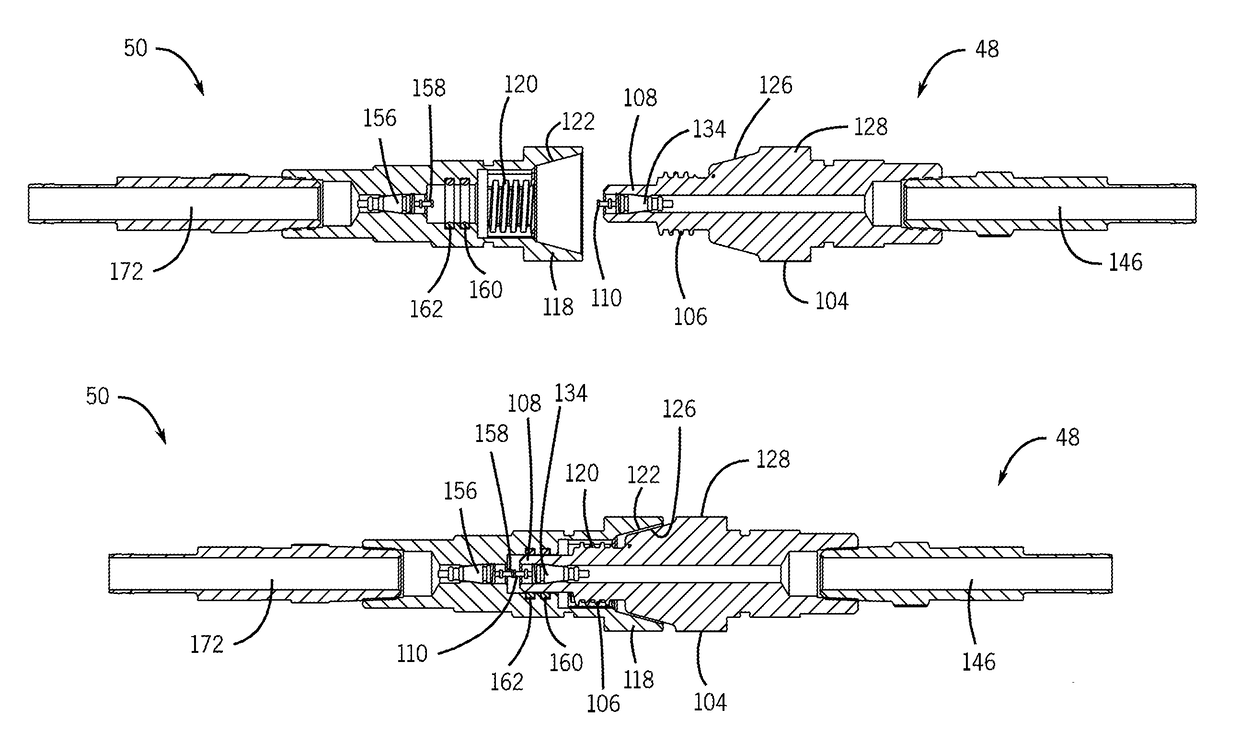
[0015]As described in detail below, embodiments of a weld electrical and gas connector with sealed gas flow are provided that may facilitate fewer components and simplified construction. For example, in certain embodiments a Schrader valve is used to control the flow of gas through the connectors, while in other embodiments a preassembled valve assembly is used to control the flow of gas through the connectors. In either case, the connectors are manufactured in a simplified manner using fewer components.

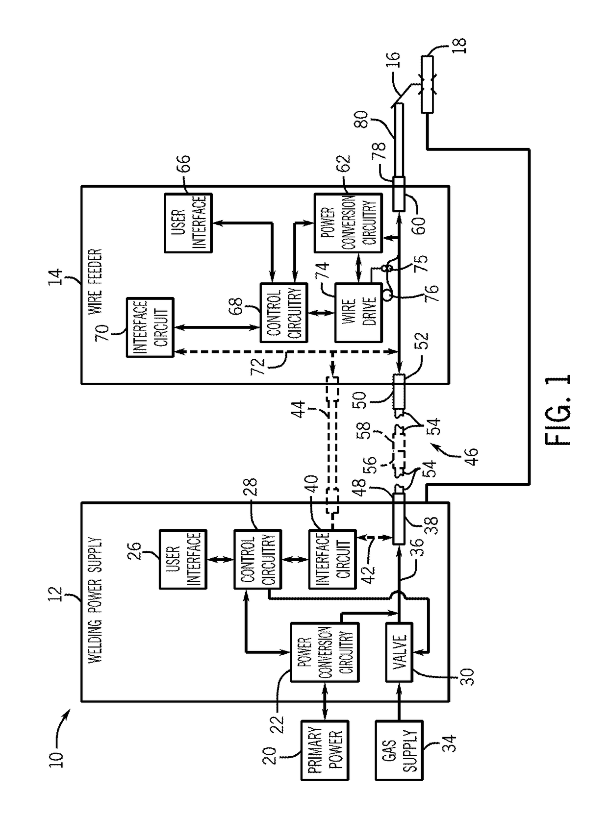
[0016]Turning now to the figures, FIG. 1 is a schematic diagram of an exemplary welding system 10 which powers, controls, and provides supplies to a welding operation. The welding system 10 includes a welding power supply 12, a wire feeder 14, a torch 16, and a workpiece 18. The welding power supply 12 receives primary power 20 (e.g., from the AC power grid, an engine / generator set, a battery, or a combination thereof), conditions the input power, and provides an output power to one ...


PUM

PropertyMeasurementUnit
radiusaaaaaaaaaa
conductiveaaaaaaaaaa
electrical conductivityaaaaaaaaaa

Abstract

A welding cable connector system having a male connector and a female connector. The male connector includes a first conductive body for conveying welding power. The male connector also includes a first sealed passageway disposed coaxially of the first conductive body for conveying shielding gas, and a first Schrader valve configured to stop flow of shielding gas when the male connector is not engaged. The female connector includes a second conductive body for conveying welding power. The female connector also includes a second sealed passageway disposed coaxially of the conductive body for conveying shielding gas, and a second Schrader valve configured to stop flow of shielding gas when the female connector is not engaged. The male and female connectors are mutually engageable to conduct welding power and shielding gas therethrough. The first and second Schrader valves seal the flow of shielding gas when the connectors are not mutually engaged.

Description

BACKGROUND[0001]The invention relates generally to welding systems and, more particularly, to a weld electrical and gas connector with sealed gas flow.[0002]Welding is a process that has become increasingly ubiquitous in various industries and applications. While such processes may be automated in certain contexts, a large number of applications continue to exist for manual welding operations. Such welding operations rely on a variety of types of equipment to ensure the supply of welding consumables (e.g., wire feed, shielding gas, etc.) is provided to the weld in an appropriate amount at the desired time. For example, metal inert gas (MIG) welding typically relies on a wire feeder to ensure a proper wire feed reaches a welding torch, as well as gas-channeling tubes or cables for routing shielding gas to the torch during the time a welding arc is created between the wire and a workpiece.[0003]Welding power sources used in such applications are designed to provide power for welding, ...

Claims


Application Information

Patent Timeline
Patent Type & Authority Patents(United States)
IPC IPC(8): B23K9/22B23K9/09B23K9/32B23K9/00
CPCB23K9/323
Inventor IHDE, JEFFERY RAYLAHTI, THOMAS DON
Owner ILLINOIS TOOL WORKS INC
Why Eureka
Try Eureka