Multi-pump-pass fiber based lasers and amplifiers

a fiber laser and amplifier technology, applied in the direction of laser details, excitation process/apparatus, active medium materials, etc., can solve the problems of high laser operation efficiency, exponential decrease, and serious challenge in designing such a system

Active Publication Date: 2018-09-18
B G NEGEV TECH & APPL LTD
View PDF11 Cites 6 Cited by
  • Summary
  • Abstract
  • Description
  • Claims
  • Application Information

AI Technical Summary

Benefits of technology

[0005]Further purposes and advantages of this invention will appear as the description proceeds.

Problems solved by technology

However, it is a very serious challenge to design such a system, due to low pump absorption in an active fiber, which diminishes exponentially upon reducing the length of the fiber.
Thus the use of short fibers as a gain medium promises to result in highly inefficient laser operation.

Method used


Image

  • Multi-pump-pass fiber based lasers and amplifiers
  • Multi-pump-pass fiber based lasers and amplifiers
  • Multi-pump-pass fiber based lasers and amplifiers

Examples


Embodiment Construction

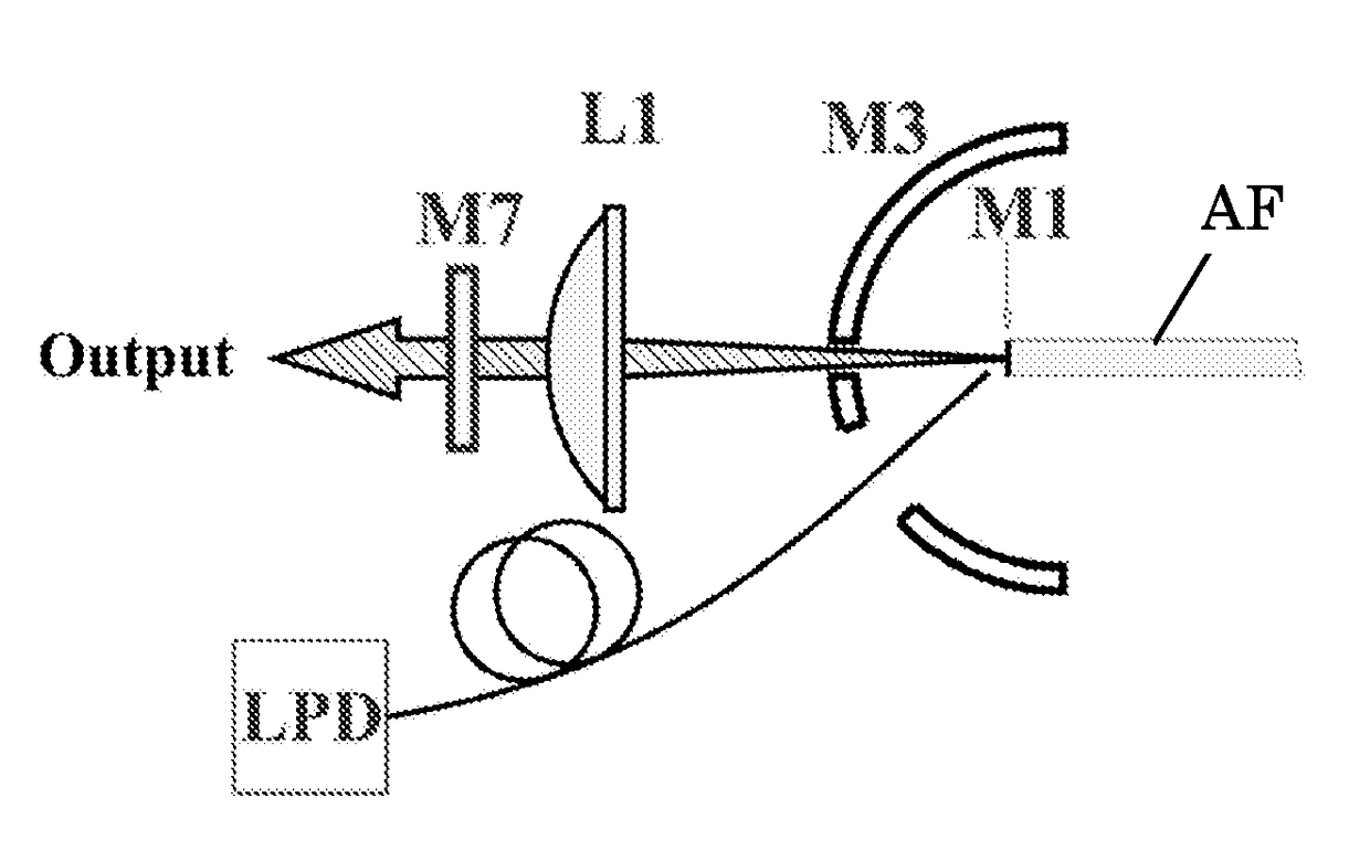
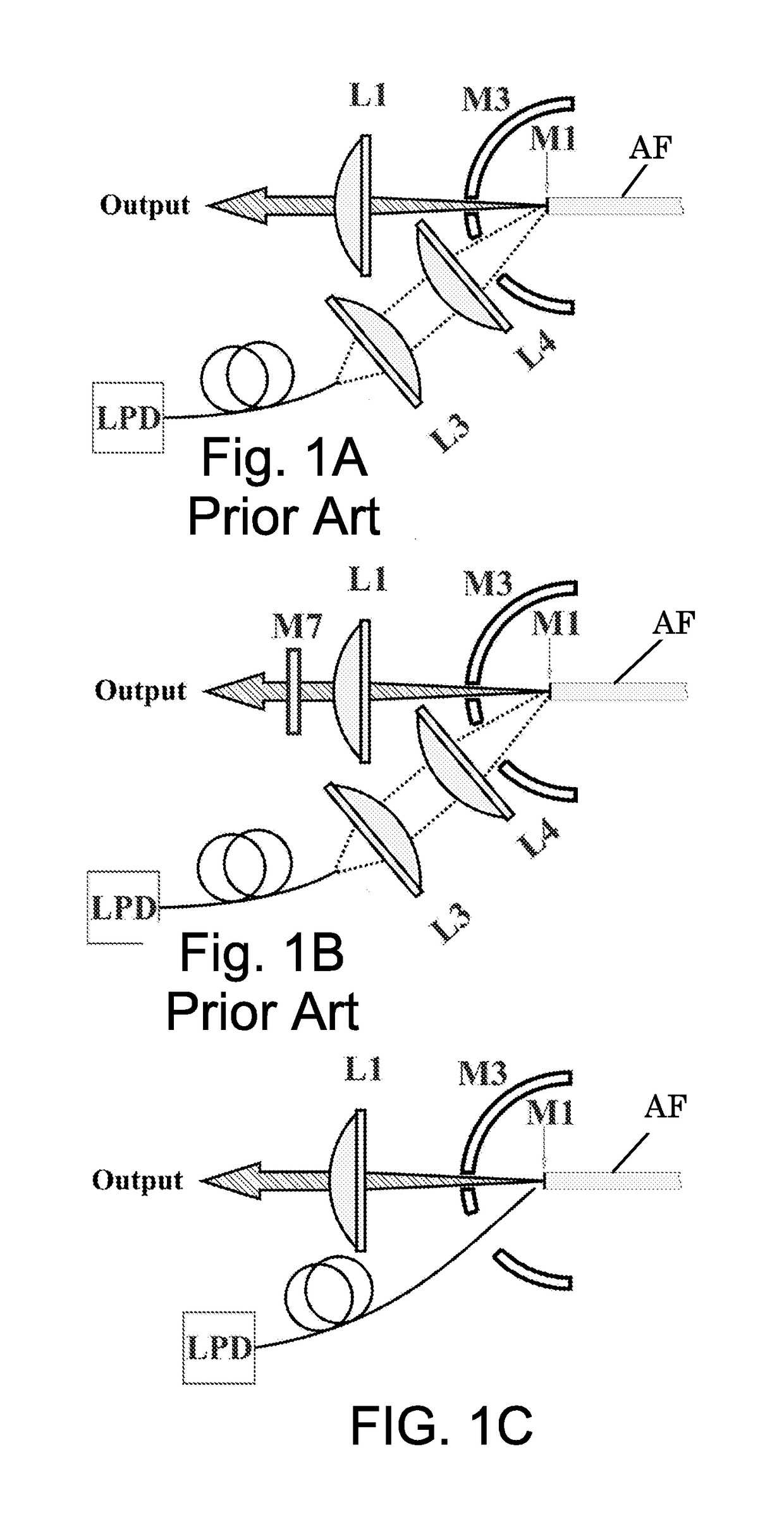
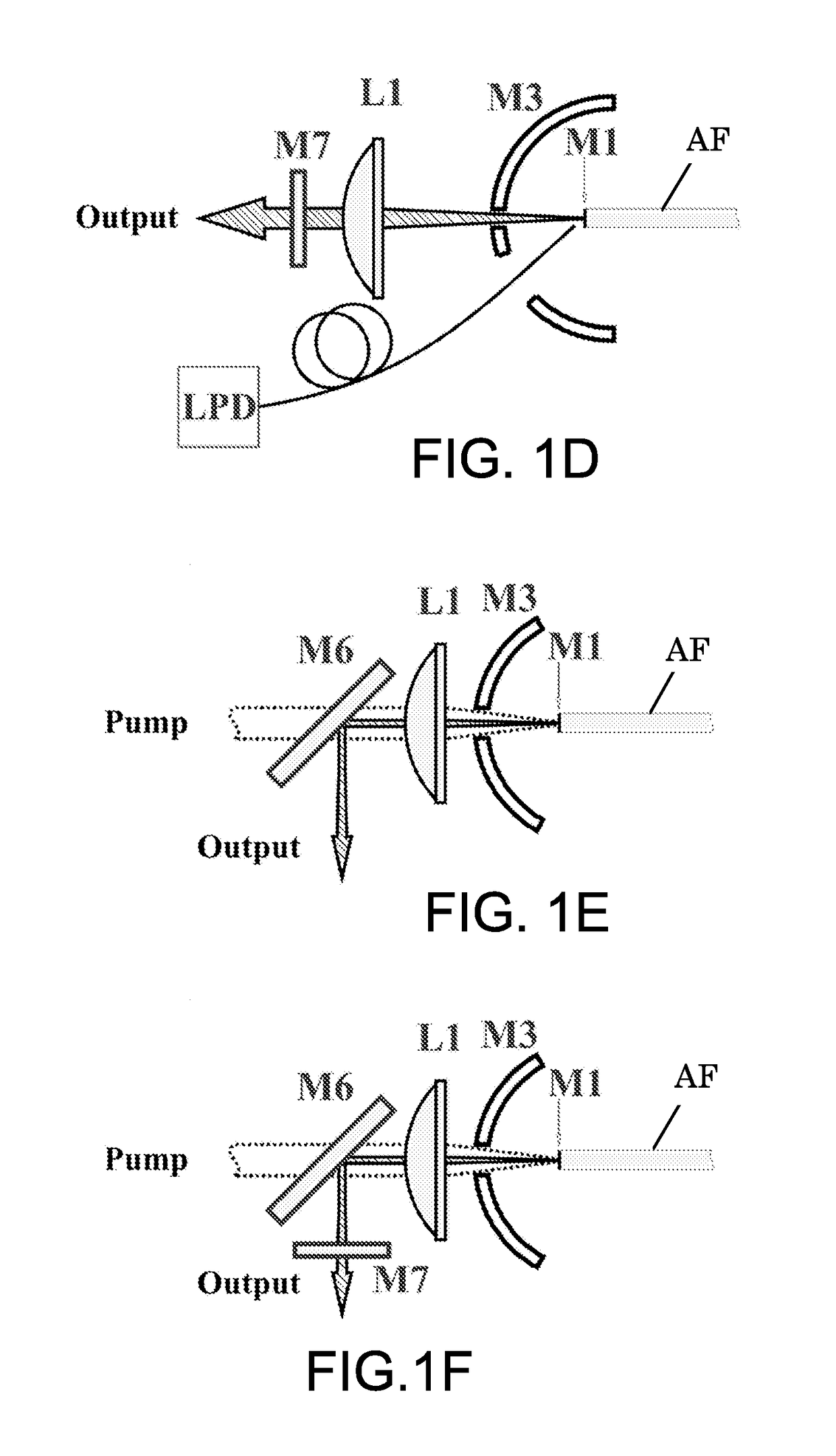
[0047]The invention is optical configurations for constructing laser oscillators or laser amplifiers that comprise an extremely short fiber (typically tens of cm long or below, e.g. 5-30 cm). In order to overcome the absorption limitation (until today, the maximal commercially available absorption is 30 dB / m @976 nm for PCFs) due to the very short length of the fiber, the present invention employees a multi pump-pass scheme for pump light confinement. This scheme is based on small angular overlap between the lasing and pump beams, which is typically the case in air clad and other special double clad fibers. The multi pump-pass method of the invention leads to fiber power oscillator lasers having a pulse duration of a few ns with high average and peak power output and with high efficiency that is comparable to the state-of-the-art fiber lasers.

[0048]In general, any laser oscillator and amplifier embodiment can be divided to a front side (the output side) and a rear side. With fiber b...


PUM


Abstract

The invention is optical configurations for constructing laser oscillators or laser amplifiers that comprise an extremely short fiber (typically tens of cm long or below, e.g. 5 cm to 30 cm). In order to overcome the absorption limitation due to the very short length of the fiber, the present invention employs a multi pump-pass scheme for pump light confinement. This scheme is based on the small angular overlap between the lasing and pump beams. The multi pump-pass method of the invention leads to efficient fiber laser oscillators and amplifiers having pulse duration of a few ns, with high average and peak power output that is comparable to the state-of-the-art solid state lasers.

Description

FIELD OF THE INVENTION[0001]The present invention relates to the field of lasers and laser amplifiers. Specifically, the invention relates to the field of optical configurations for fiber laser oscillators and amplifiers.BACKGROUND OF THE INVENTION[0002]Publications and other reference materials referred to herein are numerically referenced in the following text and respectively grouped in the appended Bibliography which immediately precedes the claims.[0003]Currently, in order to achieve high peak and average power pulses having a pulse length of a few ns with good beam quality one should use master oscillator power amplifier (MOPA) fiber systems or solid-state lasers. The reason for this is the fact that in the ns pulse range the limitation on the shortest pulse duration is the time of flight of the photon in the cavity. Accordingly, in order to achieve a 1 ns pulse the cavity should be shorter than 20 cm. Taking into account the fact that this particular cavity should include opt...

Claims


Application Information

Patent Timeline
Patent Type & Authority Patents(United States)
IPC IPC(8): H01S3/09H01S3/11H01S3/067H01S3/094H01S3/06H01S3/00H01S3/16
CPCH01S3/094015H01S3/06708H01S3/06754H01S3/094007H01S3/11H01S3/1618H01S3/005H01S3/0621H01S3/06741H01S3/094049H01S3/1123
Inventor ISHAAYA, AMIEL A.ROSENSTEIN LEVIN, BORIS
Owner B G NEGEV TECH & APPL LTD
Why Eureka
Try Eureka