Supercharge Your Innovation With Domain-Expert AI Agents!

Sludge separation system and method

a sludge separation and automatic control technology, applied in the field of sludge separation, can solve the problems of difficulty in sludge processing, rapid and easy accumulation of free fatty acids, and difficulty in cost-effective handling for meat industry, including poultry processing industry

Active Publication Date: 2018-10-02
UNIVERSAL MAINTENANCE USA LLC
View PDF3 Cites 0 Cited by
  • Summary
  • Abstract
  • Description
  • Claims
  • Application Information

AI Technical Summary

Benefits of technology

The system effectively separates valuable animal by-product nutrients from sludge, reducing waste and odor, and allows for continuous automated processing, improving the quality and recovery of Secondary Product Nutrients (SPN) for reuse, while minimizing manual labor and environmental impact.

Problems solved by technology

The meat industry, including the poultry processing industry, faced challenges with cost effective handling of sludge that results from processing.
However, free fatty acids develop quickly and build-up in the sludge.
There are difficulties with sludge processing whether for return of water to sanitary sewer systems or for further use of SPN after rendering of the processing wastes.
SPN within sludge is solid sensitive such that it is difficult to break apart properly and de-water.
Belt press devices and gravity dewatering process have been developed but there are drawbacks.
This defective product was waste and lacked value but also resulted in unpleasant plant odor.
Often sludge was transferred to landfill without recovery of the lucrative animal by-products.
The disclosed apparatus for cracking sludge, while successful, nevertheless requires significant manual labor for operating the apparatus in the practice of the process, and further, for large commercially significant meat processing facilities there is a need in the art for continuous process under automation that incorporates the batch process feature for cracking an on-going supply of ferric and non-ferric watery sludge generated by such facilities.

Method used


Image

  • Sludge separation system and method
  • Sludge separation system and method
  • Sludge separation system and method

Examples


Embodiment Construction

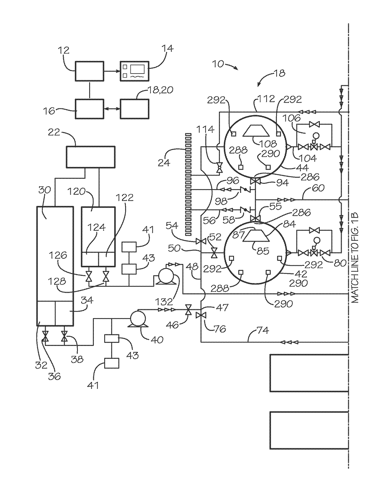
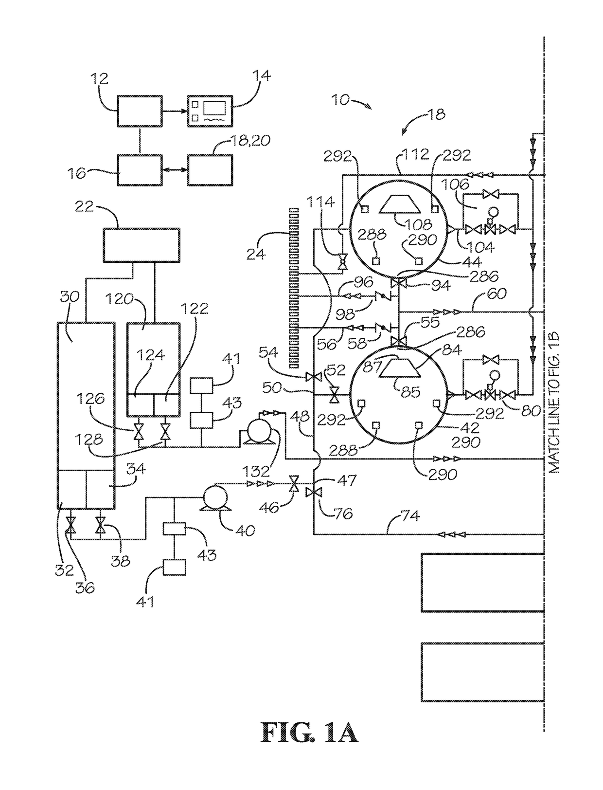
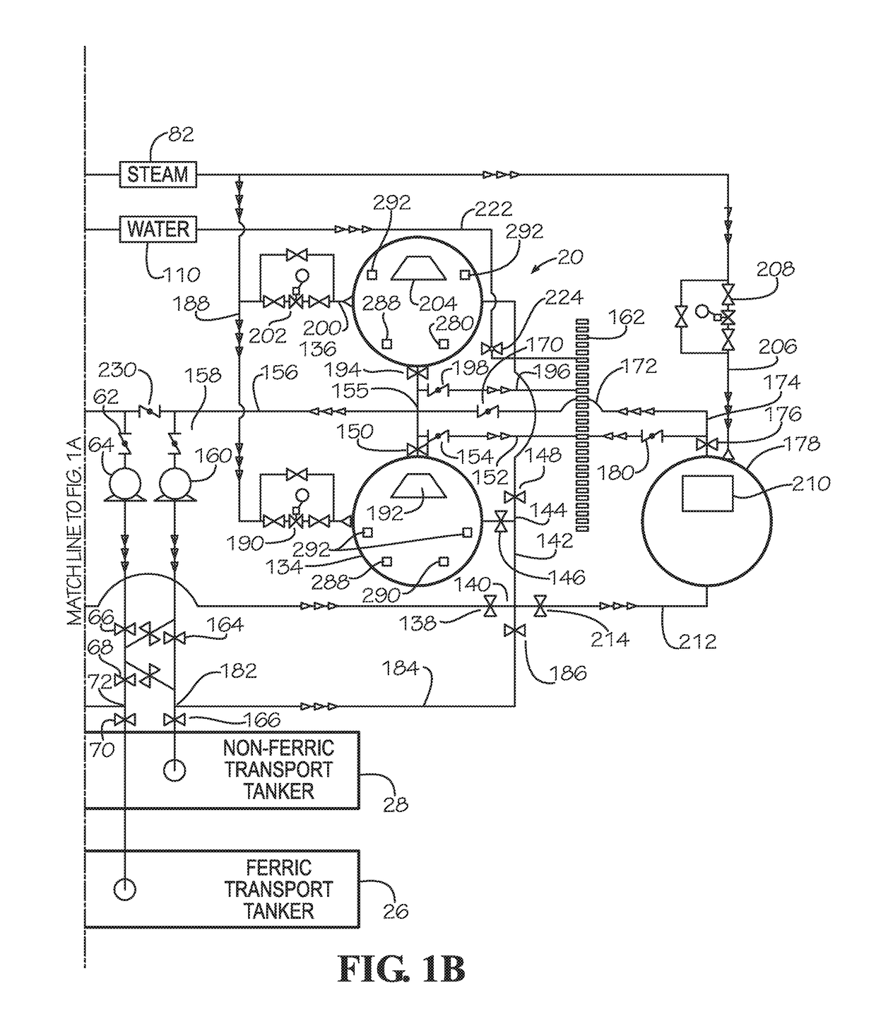
[0033]With reference to the drawings in which like parts have like reference numerals, FIGS. 1A and 1B illustrate in schematic view a sludge separation system 10 in accordance with the present invention. The sludge separation system 10 includes a microprocessor controller 12 configured with computer software programmed for supervisory control of the sludge separation system, data acquisition from various valves (actuators and position indicating switches) and sensors of the sludge separation system, and display of system status and alerts on a display 14 for an operator to monitor the equipment and process, direct actions of the system, and to enter data and commands as appropriate during operation of the system. The controller 12 communicates with a programmable logic controller 16 (PLC 16) that directly connects to system monitoring and control devices (pumps, valves, sensors, push-buttons and the like) for monitoring and operational control.

[0034]The sludge separation system 10 i...


PUM

PropertyMeasurementUnit
temperatureaaaaaaaaaa

Abstract

A system and method for cracking sludge, comprising first and second decant vessels for receiving and continuous processing, which decant vessels include an outlet for decanting selectively separated watery residue to a drain and cracked decanted SPN solids to a transport, with graduated heat matrix processing of the sludge at sensor-monitored temperature and dwell time for cracking the sludge, and a programmable controller responsive to temperature and level sensors for adjusting the heat media communicated through the heat matrix and for determining completion of a sludge cracking process, with a heat member providing pre-process agitation of the sludge as an influent filing the decant vessel and elevating the temperature to a pre-process temperature over ambient.

Description

TECHNICAL FIELD[0001]The present invention relates to the field of sludge separation that recovers by-product nutrients while minimizing waste residuals for disposal and returning clarified water to sanitary water supply systems for processing and discharge. More particularly, the present invention relates to automation control of sludge separation systems.BACKGROUND OF THE PRESENT INVENTION[0002]The meat industry, including the poultry processing industry, faced challenges with cost effective handling of sludge that results from processing. Sludge originates as the watery waste from meat processing and from cleaning of the process facilities. By volume, sludge is primarily water, but sludge also contains waste such as bone chips, skin parts, animal by-products, and scraps, of which some is valuable animal fat, protein and other nutrients. Efforts are made to extract at least some of the water from the sludge, such as by drainage from holding tanks, for subsequent transfer of the at...

Claims


Application Information

Patent Timeline
Patent Type & Authority Patents(United States)
IPC IPC(8): C02F11/18C02F11/12C02F1/00C02F1/24C02F11/13C02F103/22
CPCC02F11/18C02F11/12C02F11/185C02F1/24C02F2001/007C02F2301/08C02F2209/005C02F2209/02C02F2209/10C02F2209/42C02F2103/22C02F11/13
Inventor HILL, RILES EDWARD
Owner UNIVERSAL MAINTENANCE USA LLC
Features
  • R&D
  • Intellectual Property
  • Life Sciences
  • Materials
  • Tech Scout
  • Unparalleled Data Quality
  • Higher Quality Content
  • 60% Fewer Hallucinations
Learn More