Ground milling machine having a cooling system, cooling system, and method for cooling a ground milling machine

a cooling system and ground milling machine technology, applied in mechanical equipment, engine cooling apparatus, constructions, etc., can solve the problems of reducing the total cooling power of the cooling system, comparatively high fuel consumption, and high power demand of the fan, so as to achieve energy-efficient cooling, high volume flow, and maximum power

Active Publication Date: 2018-10-16
BOMAG
View PDF19 Cites 3 Cited by
  • Summary
  • Abstract
  • Description
  • Claims
  • Application Information

AI Technical Summary

Benefits of technology

[0025]A special advantage of the present invention comes to bear when the first fan and the second fan are implemented so as to be controllable independently from each other. In other words, the volume flows transported by the respective fans can be set individually, or separately, from each other. This is achieved especially via a control and change in the fan speed. Especially energy-efficient cooling can be achieved with respect to the initially mentioned alternating loads of the internal combustion engine and the hydraulic system in a ground milling machine by a first and second fan which can be controlled independently from each other. Accordingly, the first fan can be operated in working operation with running milling drum of the ground milling machine at high fan speed and thus with a high volume flow and substantially maximum power, whereas the second fan is operated at a relatively low fan speed and thus with a low volume flow or power. In contrast, the second fan can be operated at high fan speed during travelling operation of the ground milling machine and thus at high volume flow and substantially maximum power, whereas the first fan is operated at low fan speed and with lower power. The control of the power of the first fan and the second fan as well as the closed-loop control of the respectively achieved volumetric flow more preferably occurs automatically by a control device depending on an objective control variable, for example, the temperatures of the cooling liquid of the cooling circuit for the internal combustion engine and the hydraulic oil of the hydraulic system. A further control variable may also be the engine compartment temperature which must not exceed a predetermined maximum value. If passage openings are provided between the engine compartment and the second cooling air duct, the control device can also trigger the second fan depending on the temperature of the cooling liquid of the cooling circuit for the internal combustion engine. As a result of the independent adjustment of the fan speeds and thus the volume flow of the cooling air in the first and second cooling air duct, it is ensured that the fans are only operated at high power when this is required for cooling the internal combustion engine or the hydraulic system. The closed-loop control of the fan speeds thus occurs individually and needs-oriented, by means of which the energy consumption of the ground milling machine can be reduced significantly.
[0026]In order to achieve an even more individual adjustment of the fan power, it has proven to be advantageous if the hydraulic fluid cooling device comprises a third fan in addition to the second fan, wherein the second fan and third fan are controllable independently from each other. The second fan and the third fan are further ideally arranged considerably smaller with respect to their respective performance specifications than the first fan of the engine cooling device. A more precise closed-loop control can thus be provided especially in the lower power range of the hydraulic fluid cooling device and a total fan power can thus be provided which is adjusted even more optimally to the respective cooling requirements. Especially in the case of low to medium loading of the hydraulic system, power can be saved by the operation of a second and third fan which are smaller in size in comparison to the first fan. It is also possible to operate even only the second or the third fan depending on the requirements. The second and third fan are preferably also controlled by the control device, which also controls the first fan, although a separate control of the first fan with a separate control device is also possible.
[0027]It is frequently advantageous to cool further components of the ground milling machine via at least one further cooling circuit in addition to the cooling of the internal combustion engine and the hydraulic system. Cooling devices for cooling the milling gear and / or pump transfer gear, etc., can be provided, for example. It is ideal if said additional cooling devices are structurally integrated in the first and / or second cooling air duct in order to keep additional costs for construction work as low as possible.
[0028]Accordingly, it is preferable, for example, to arrange an additional heat exchanger in the first cooling air duct of the engine air cooling device, which additional heat exchanger is connected to a cooling circuit for cooling the milling gear, wherein the additional heat exchanger is arranged adjacent to the engine heat exchanger, and especially above said heat exchanger. A cooling liquid thus flows through the additional heat exchanger, which is used for cooling the milling gear with which drive power is transferred from the internal combustion engine to the milling drum. The additional heat exchanger is arranged adjacent to and especially above the engine heat exchanger in such a way that the cooling air of the first cooling air duct also flows through the additional heat exchanger. The arrangement of the engine heat exchanger and the additional heat exchanger as well as the first cooling air duct is preferably made in such a way that cooling air either flows through the engine heat exchanger or the additional heat exchanger, but not through both heat exchangers. It is thus ensured that “fresh” cooling air always flows through the respective heat exchanger and thus provides for maximum removal of heat from the respective heat exchanger. The arrangement of the additional heat exchanger adjacent to and especially above the engine heat exchanger also ensures that the two heat exchangers are pre-mounted outside of the ground milling machine, for example, which facilitates mounting.
[0029]It is additionally, or alternatively, preferable that an additional heat exchanger is present in the second cooling air duct of the hydraulic fluid cooling device, which additional heat exchanger is connected to a cooling circuit for cooling the pump transfer gear, wherein the additional heat exchanger is arranged adjacent to and especially above the hydraulic fluid heat exchanger. The statements made above concerning the heat exchanger additionally arranged in the engine cooling device apply similarly to said additional heat exchanger which is arranged in the second cooling air duct. A cooling liquid of a cooling circuit for cooling the pump transfer gear flows through the additional heat exchanger of the hydraulic fluid cooling device and ensures that it is sufficiently cooled. The cooling air which flows through the additional heat exchanger is conveyed by the second and optionally the third fan. Mounting of the ground milling machine is again promoted by joint installation of a pre-mounted unit of the hydraulic fluid heat exchanger and the additional heat exchanger.
[0030]An embodiment has proved to be especially preferred with respect to mounting and maintenance work of the cooling system on the ground milling machine in which a common retaining frame is present, on which the engine cooling device and the hydraulic fluid cooling device, and especially also the first separating wall and / or the second separating wall, are mounted. A retaining frame designates a contiguous, particularly frame-like support structure on which the respective aforementioned components are fixed and retained. The retaining frame can either be arranged firstly in the ground milling machine and then comprise receivers for the individual components of the cooling system, or it can also be pre-mounted outside of the ground milling machine with the respective components of the cooling system and subsequently be installed as a modular unit or a contiguous cooling assembly in the ground milling machine. The retaining frame is implemented in its entirety for accommodating at least two of the components of engine heat exchanger, first fan, parts of the cooling circuit for the cooling liquid of the internal combustion engine, hydraulic fluid heat exchanger, second and / or third fan, first separating wall, second separating wall, internal combustion engine, heat exchanger for the milling drum gear, heat exchanger for the pump transfer gear, and further components or boundaries of the first and / or second cooling air duct. The retaining frame can also be a part of the boundary of the engine compartment or the enclosure of the internal combustion engine as well as a part of the first and second cooling air duct which also conducts cooling air at least in sections.

Problems solved by technology

However, this partly considerably reduces the total cooling power of the cooling system, since, in this case, only cooling air that has already been heated to some extent is available for the hydraulic fluid heat exchanger, for example.
This leads to a high power demand of the fan and thus especially also to a comparatively high share in the fuel consumption which is incurred for the operation of the fan alone.
In the ground milling machines and methods for cooling as known from the prior art and as described above, it is disadvantageous that oversized cooling devices are regularly used in order to ensure efficient cooling both of the internal combustion engine and also the hydraulic fluid even under peak loads.

Method used


Image

  • Ground milling machine having a cooling system, cooling system, and method for cooling a ground milling machine
  • Ground milling machine having a cooling system, cooling system, and method for cooling a ground milling machine
  • Ground milling machine having a cooling system, cooling system, and method for cooling a ground milling machine

Examples


Embodiment Construction

[0056]Like components are provided with like reference numerals. Repeated components are partly not designated individually in each drawing.

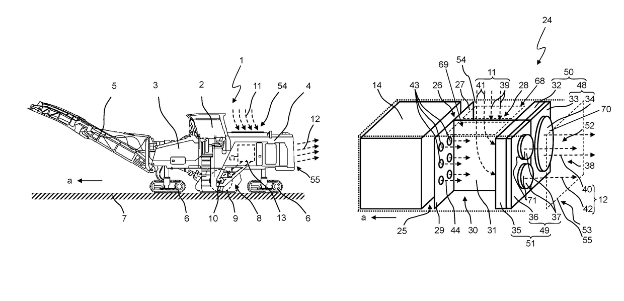
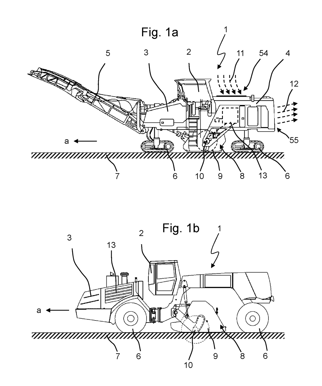
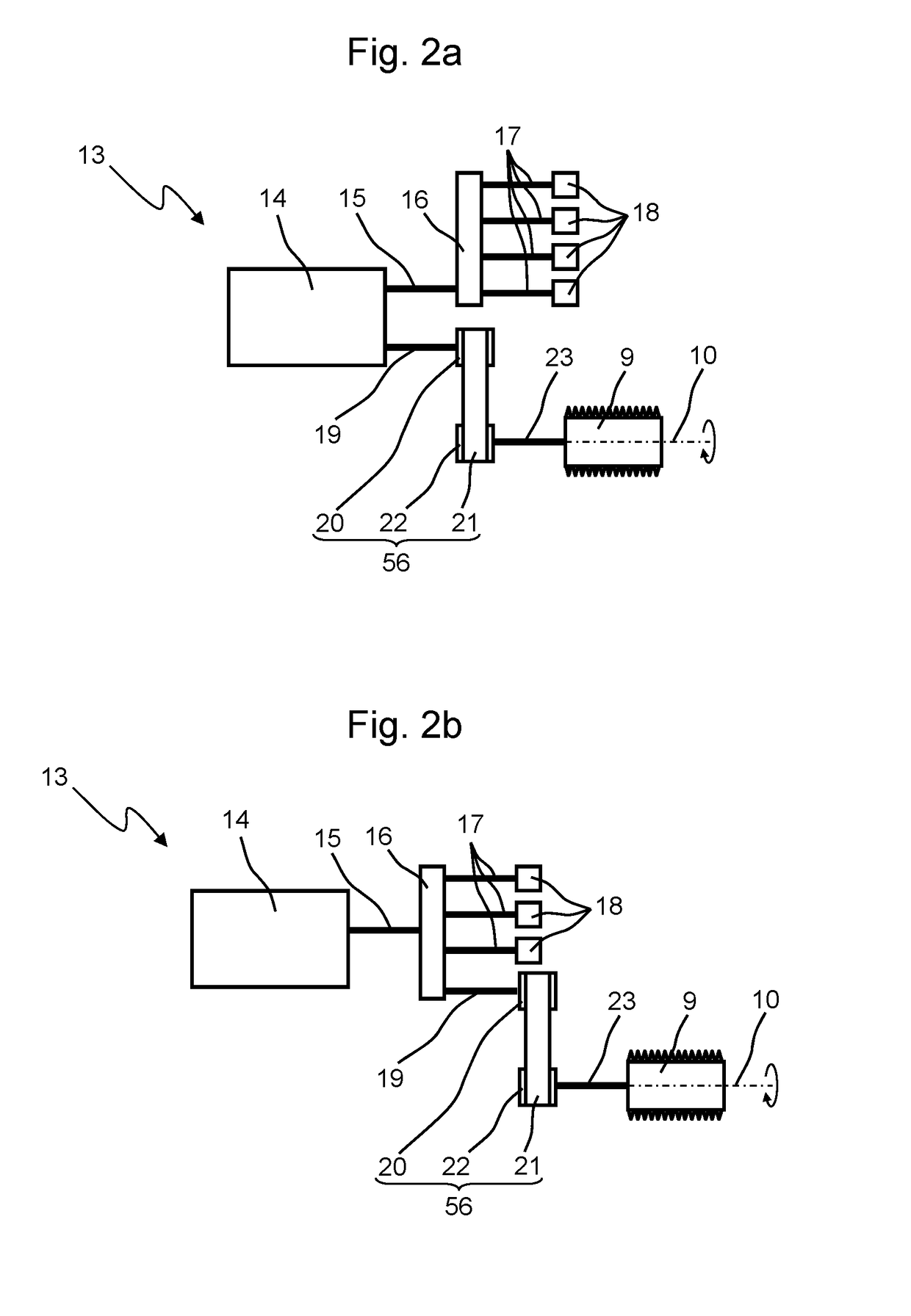
[0057]FIG. 1a shows a ground milling machine 1 of the type of a road cold milling machine (center rotor milling machine), comprising an operator platform 2 and a machine frame or chassis 3. The ground milling machine 1 moves in the working direction a over the ground 7 to be processed by using the running gears 6. The ground milling machine 1 mills the ground 7 by means of a milling drum 9 which is mounted in a milling drum box 8 so as to rotate about the rotational axis 10. The removed milling material can be transferred in the working direction a via a discharge device 5, e.g., a discharge conveyor in a pivotable discharge arm, to a transport vehicle not shown here, and can be removed by said vehicle. The ground milling machine 1 further comprises a drive train 13 which is shown in closer detail in FIG. 2a or 2b. In order to cool components of...


PUM


Abstract

The present invention relates to a ground milling machine with two cooling ducts, which allow a mutually separated guidance of cooling air. The present invention further relates to such a cooling system and a method for cooling a ground milling machine.

Description

CROSS-REFERENCE TO RELATED APPLICATION[0001]The present application claims priority under 35 U.S.C. § 119 of German Patent Application No. 10 2014 008 749.2, filed Jun. 12, 2014, the disclosure of which is hereby incorporated herein by reference in its entirety.FIELD OF THE INVENTION[0002]The present invention relates to a ground milling machine, especially a cold milling machine, a stabiliser or recycler, a cooling system, and a method for cooling such a ground milling machine.BACKGROUND OF THE INVENTION[0003]A generic ground milling machine, especially a cold milling machine, a stabiliser or recycler, having a cooling system is known, for example, from DE 103 47 872 C5. Such ground milling machines are frequently used in road and path construction as well as for subgrade stabilisation. Their working device is a cylindrically shaped milling drum which is equipped on its outside circumference with a plurality of milling tools. In working operation of the ground milling machine, the ...

Claims


Application Information

Patent Timeline
Patent Type & Authority Patents(United States)
IPC IPC(8): B60K11/00F01P11/10E01C23/088F01P3/18F01P5/02
CPCF01P11/10E01C23/088F01P2005/025F01P2003/185E01C23/12
Inventor BALDUS, MATTHIASSTEIN, DIANAHAMMES, MANFREDMUDERS, NILS
Owner BOMAG
Why Eureka
Try Eureka