
Ultrasonic particle size measurement device and ultrasonic measurement device

a measurement device and ultrasonic technology, applied in measurement devices, particle and sedimentation analysis, instruments, etc., can solve the problems of difficult light transmission, difficult to carry out measurement with respect to turbid samples, etc., and achieve favorable sn ratio, high accuracy, and rapid motion

Active Publication Date: 2018-10-16
NAT UNIV KYOTO INST OF TECH
View PDF16 Cites 0 Cited by
  • Summary
  • Abstract
  • Description
  • Claims
  • Application Information

AI Technical Summary

Benefits of technology

The ultrasonic particle size measurement device described in this patent has two main technical effects. The first effect is that it can accurately measure the size of fine particles in relatively rapid motion using high-resolution ultrasonic signals. The second effect is that it can measure the size of fine particles in slow motion by inducing an ultrasonic fine particle velocity in the particles and calculating the scattered wave generated by the induced velocity using a high signal-to-noise ratio. These technical effects provide a valuable tool for researchers to study the properties and behavior of fine particles in different environments and applications.

Problems solved by technology

Note, however, that the dynamic light scattering method has the following problem.
Specifically, according to the dynamic light scattering method, only a sample that is relatively transparent to laser light is analyzed, and it is difficult to carry out measurement with respect to a turbid sample, which is less light-transmissive.
Thus, according to the dynamic ultrasound scattering method, difficulty in light transmission depending on, for example, whether a sample is colored or uncolored does not matter.

Method used


Image

  • Ultrasonic particle size measurement device and ultrasonic measurement device
  • Ultrasonic particle size measurement device and ultrasonic measurement device
  • Ultrasonic particle size measurement device and ultrasonic measurement device

Examples


embodiment 1

[0064](Overview of Embodiment 1)

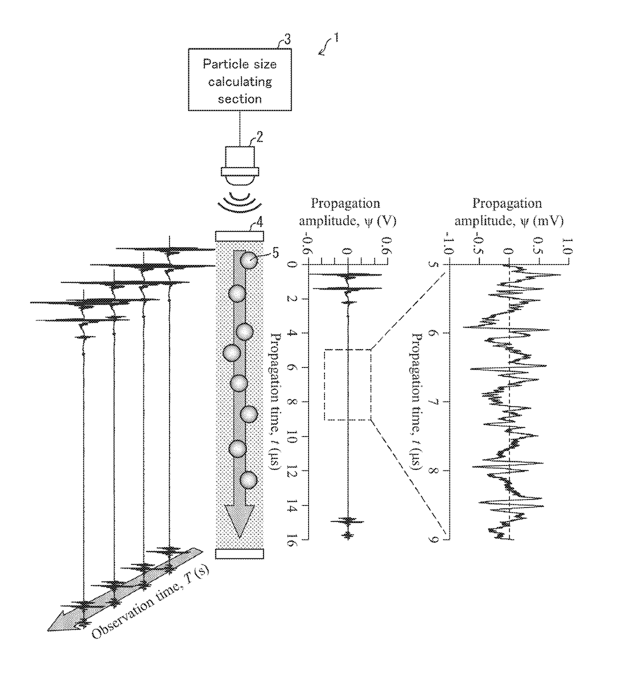
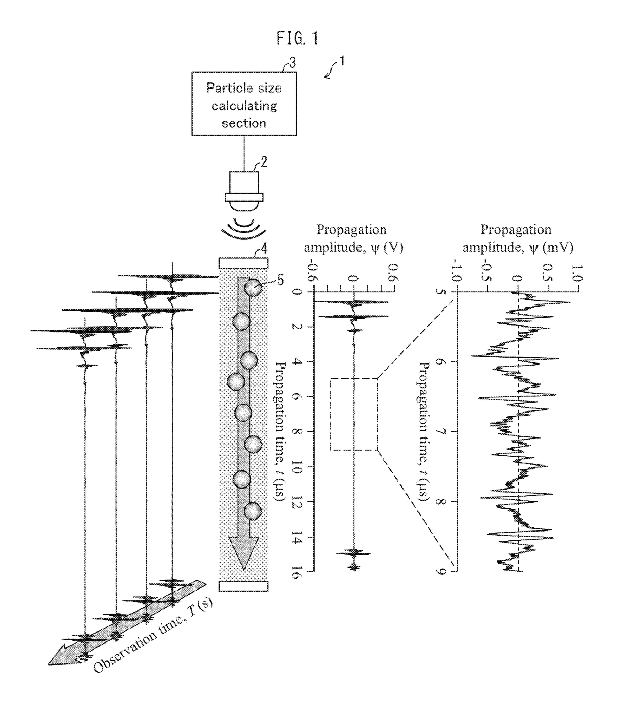
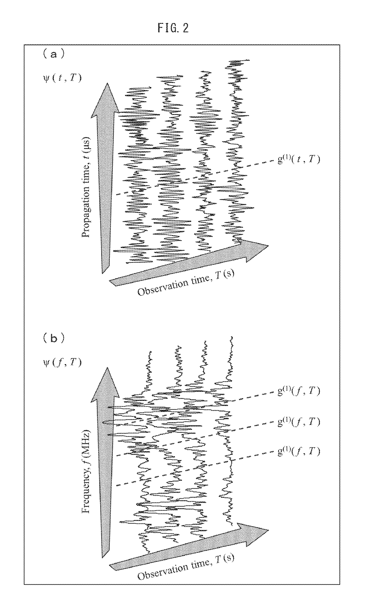
[0065]The reason why a measurement error of approximately 10% occurs in a particle size measured by the conventional dynamic ultrasound scattering method (Non-patent Literature 5) is largely due to the fact that emitted light is a laser having a narrow wavelength distribution, whereas an ultrasonic pulse is a “broadband” pulse having a broad wavelength distribution and constituted by an emitted wave containing various frequency components. An ultrasonic pulse that allows various broad frequency bands to be covered by measurement carried out one time is convenient in a spectroscopy experiment in which frequency analysis is carried out. Such a distribution of various frequency components inhibits precise determination of a location of a particle at a given instantaneous time and a particle size. According to Embodiment 1, an ultrasonic pulse obtained along a time axis is subjected to a Fourier transform and analyzed in a frequency space. It has been con...

embodiment 2

[0129](Overview of Embodiment 2)

[0130]Embodiment 2 allows particle size measurement to be carried out at a higher S / N ratio and in a shorter time in a case where a particle moves at an extremely low velocity. Embodiment 2 proposes a method in which great ultrasonic energy is intentionally externally applied to fine particles (dispersoids) dispersed into a liquid (dispersion medium) and a particle size of the fine particles is calculated from a velocity (ultrasonic fine particle velocity) induced in the fine particles by the application of the ultrasonic energy. Note that the conventional dynamic ultrasound scattering method in which a particle size is found in accordance with a sedimentation velocity is a simple and easy particle size measuring method with respect to a fine particle. Note, however, that according to the conventional dynamic ultrasound scattering method, it is necessary to start measurement after waiting for a fine particle to reach a state of steady motion. Thus, a ...


PUM

PropertyMeasurementUnit
particle sizeaaaaaaaaaa
frequencyaaaaaaaaaa

Abstract

An ultrasonic particle size measurement device includes: a transducer for (i) receiving an ultrasonic pulse scattered after being emitted to a fine particle and (ii) generating a first scattering amplitude Ψ; and a particle size calculating section for calculating a particle size of the fine particle by calculating an amplitude r and a phase θ in accordance with a real part and an imaginary part, respectively, of a second scattering amplitude Ψ obtained by subjecting the first scattering amplitude Ψ to a Fourier transform.

Description

TECHNICAL FIELD[0001]The present invention relates to an ultrasonic particle size measurement device for measuring, by use of an ultrasonic pulse, a particle size of fine particles (dispersoids) dispersed into a liquid (dispersion medium).BACKGROUND ART[0002]It is known that a diffusion constant and a hydrodynamic radius (particle size) of a fine particle having a particle size of approximately 1 nanometer (nm) to 3 micrometers (μm) can be quantified by a dynamic light scattering (DLS) method [Non-patent Literature 1]. In a case where laser light that is highly coherent is emitted to a solution sample obtained by dispersing particles into a solution, scattering of the laser light is observed depending on a size and a shape of the particles in the solution, and an intensity of the laser light changes over time in accordance with motion of the particles. In this case, it is empirically and theoretically clear that Brownian motion of a smaller particle can be seen as the intensity more...

Claims


Application Information

Patent Timeline
Patent Type & Authority Patents(United States)
IPC IPC(8): G01N15/02G01N29/24G01N29/46G01N29/032G01N29/024
CPCG01N15/0211G01N15/02G01N29/024G01N29/032G01N29/46G01N2291/02416G01N2015/0216G01N2015/0222G01N2291/0289G01N2015/0053G01N15/04G01N2015/0277
Inventor NORISUYE, TOMOHISA
Owner NAT UNIV KYOTO INST OF TECH
Learn More