Method for determining the power consumption of a programmable logic device

a programmable logic and power consumption technology, applied in the direction of instruments, special data processing applications, electric digital data processing, etc., can solve the problems of critical consequences, large dependence on the dynamic significant increase in the power consumption of the fpga, so as to achieve the effect of realizing the dynamic power consumption

Active Publication Date: 2018-10-16
DSPACE DIGITAL SIGNAL PROCESSING & CONTROL ENG
View PDF12 Cites 0 Cited by
  • Summary
  • Abstract
  • Description
  • Claims
  • Application Information

AI Technical Summary

Benefits of technology

[0012]It is therefore an object of the invention to provide a method and a device that advance the state of the art and make possible a realistic estimate of the dynamic power consumption for the specific application case.

Problems solved by technology

A general problem in the use of programmable logic devices is that the dynamic power consumption of the FPGA depends heavily on the configuration, which is to say in particular the controller model being implemented, and on the stimuli, which is to say the signals present at the interface pins.
Since changes at the interface pins can propagate through the entire FPGA and result in repeated switching of logic gates during a single clock, a high rate of change of the stimuli causes a significantly increased power consumption by the FPGA.
When FPGAs are used in an RCP system, this can have critical consequences if the resultant waste heat overloads a passive cooling system or the power supply.
While the manufacturers are well able to take into account the structural characteristics of the programmable logic device and the characteristics of the manufacturing process used, it is still the case that the dynamic behavior of a specific configuration can be described only with limited accuracy for reasons that include simplifying assumptions.

Method used


Image

  • Method for determining the power consumption of a programmable logic device
  • Method for determining the power consumption of a programmable logic device
  • Method for determining the power consumption of a programmable logic device

Examples


Embodiment Construction

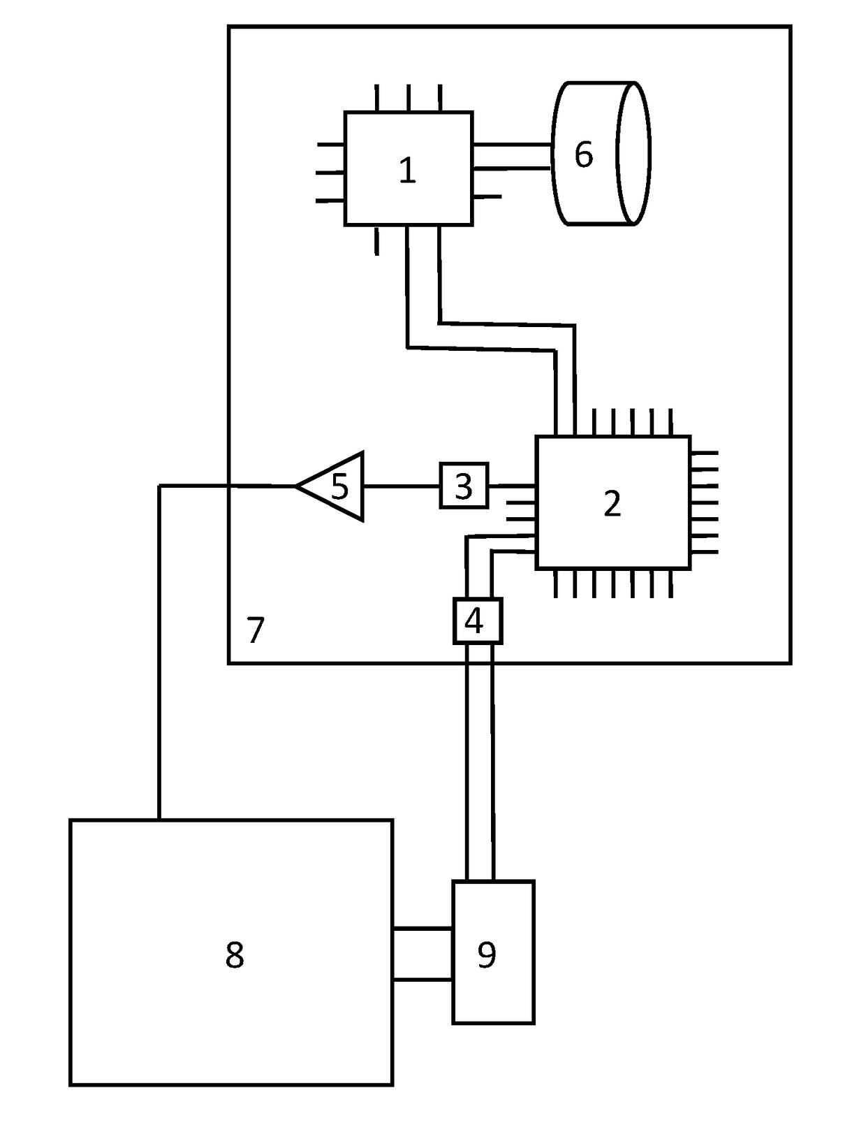
[0045]The illustration in FIG. 1 shows a schematic representation of a control unit 7, which is used in the example shown for driving an electric machine 8. The invention is applicable, in general, to any desired type of driven actuators and any desired type of control.

[0046]The control unit 7 comprises a microprocessor 1 and a programmable logic device 2, which are connected to one another through a data bus. The data bus can include any desired number of lines, in general; for reasons of clarity, only two lines are shown. The microprocessor 1 is connected to a nonvolatile memory 6, which can also be implemented as part of the microprocessor. During initialization of the control unit 7, the program executed by the microprocessor 1 and the configuration of the programmable logic device 2 can both be read out from the nonvolatile memory 6. The microprocessor 1 can have digital and analog interfaces and, for example, can be connected to a transceiver, not shown, of a vehicle data bus....


PUM


Abstract

A method for determining the power consumption of a programmable logic device, in which at least one configuration parameter is determined in accordance with a predefined configuration and at least one device parameter is determined in accordance with the programmable logic device. The predefined configuration is designed such that the programmable logic device exchanges data with a computing unit through at least one interface pin and receives data from at least one signal source and / or sends it to at least one signal receiver through at least one interface pin. At least one data characteristic of the data exchanged between the computing unit and the programmable logic device as well as at least one signal characteristic of the data received from the at least one signal source and / or sent to the at least one signal receiver are determined.

Description

[0001]This nonprovisional application claims priority under 35 U.S.C. § 119(a) to German Patent Application No. 10 2015 118 129.0, which was filed in Germany on Oct. 23, 2015, and which is herein incorporated by reference.BACKGROUND OF THE INVENTION[0002]Field of the Invention[0003]The invention relates to a method for determining the power consumption of a programmable logic device, a method for designing a configuration of a programmable logic device, and a programming device for writing on a programmable logic device.[0004]Description of the Background Art[0005]In many technical fields, control units are used to control a physical process, wherein new measured values are acquired, preferably cyclically, from one or more sensors, and one or more actuators are driven on the basis of a comparison of the measured values with setpoint values. For rapid design of new control units and / or control algorithms, it is possible to build on an existing control unit and simply replace individu...

Claims


Application Information

Patent Timeline
Patent Type & Authority Patents(United States)
IPC IPC(8): G06F17/00G06F17/50
CPCG06F17/5054G06F17/5036G06F17/5022G06F2217/78G06F30/33G06F30/34G06F30/367G06F2119/06
Inventor LUBELEY, DOMINIKSCHLENGER, MARCKALTE, HEIKO
Owner DSPACE DIGITAL SIGNAL PROCESSING & CONTROL ENG
Why Eureka
Try Eureka