Power handling system and method

a power handling system and power technology, applied in the field of circuit assemblies, can solve the problems of limited current supply to devices, limited power consumption of drivers and light sources from the grid, and inability to influence the load on the control bus, etc., to achieve easy connection, high power load, and high power load

Inactive Publication Date: 2018-10-16
GE LIGHTING SOLUTIONS LLC
View PDF16 Cites 1 Cited by
  • Summary
  • Abstract
  • Description
  • Claims
  • Application Information

AI Technical Summary

Benefits of technology

[0005]In one embodiment, a power handling system and method are provided to allow a high current relay to be switched on or off with a small amount of current supplied by a digitally addressable interface (DALI) lighting system. The relay can be switched on to cause a higher power load (e.g., a load that could not be powered by the DALI lighting system) to be activated. The higher power load may be powered by another power source, such as a utility grid, that supplies a larger amount of voltage and / or current (e.g., 110 volts / 230 volts AC) than is provided by the DALI lighting system. This allows for the higher power loads to be more easily connected with the DALI lighting system in that additional wires or buses may not be needed (or very few additional wires or buses are needed), and may allow for IEC class II safety separation for appliances.

Problems solved by technology

As a result, the power consumption of the drivers and light sources from the grid does not have an impact on the load on the control bus.
But, because the control bus may be limited in the amount of power it can supply (e.g., 250 milliamps or less of turnover current), the amount of current that can be supplied to the devices is limited.
As a result, the number of these devices that can be included in the DALI system may be limited (e.g., to two devices or less), or the devices may only be able to operate on very limited amounts of power from the DALI control bus.
Consequently, devices such as incandescent light sources, light sources having tungsten filaments, or other devices (e.g., other than light sources) may not be connected directly with the DALI lighting system.
The additional power may be needed because switching high loads from a low power digital bus can require expensive high current relays with an alternating current mains bus providing the power to the relays or two or more relay stages that can be expensive and complicated or impossible in some cases.

Method used


Image

  • Power handling system and method
  • Power handling system and method
  • Power handling system and method

Examples


Embodiment Construction

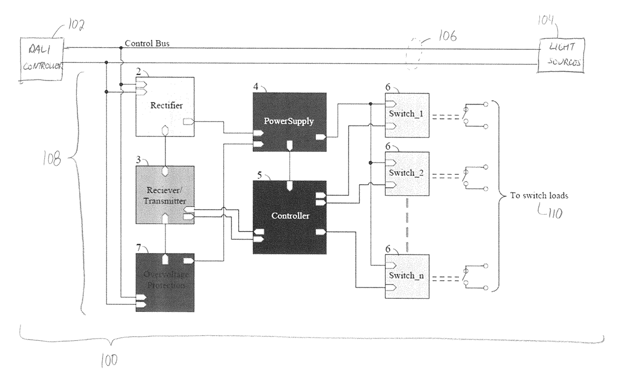
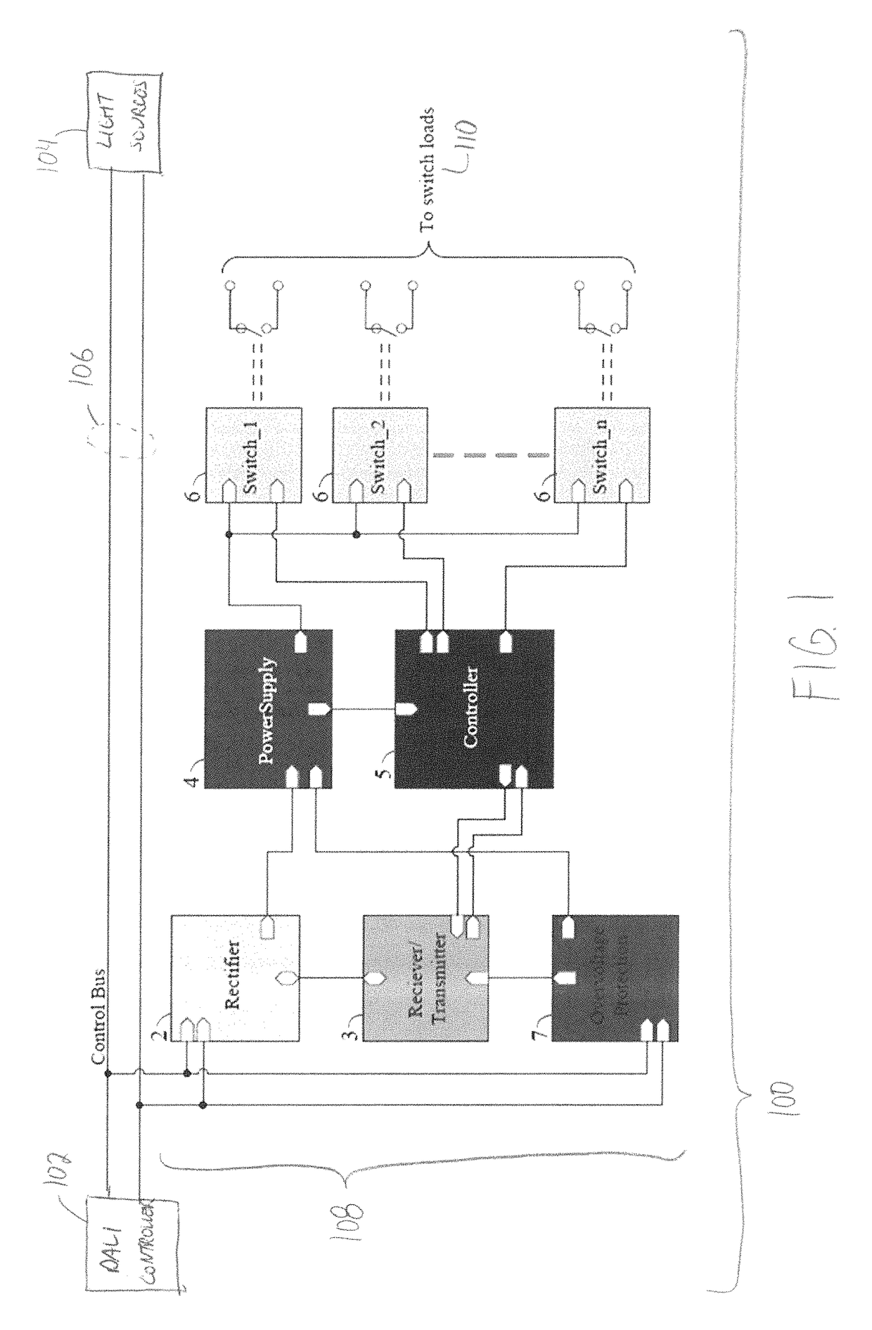
[0015]FIG. 1 illustrates a lighting system 100 having a power handling system 102 according to one example. The lighting system 100 includes a lighting controller 102 (e.g., “DALI controller” in FIG. 1) that controls operation of one or more low or lower power light sources 104. The controller 102 can represent hardware circuitry that includes and / or is connected with one or more processors (e.g., microcontrollers, microprocessors, field programmable gate arrays, integrated circuits, etc.). The light sources 104 may represent one or more LEDs or other types of light sources that operate on reduced amounts of current, such as less than 20 milliamps, less than 10 milliamps, or the like, and / or on reduced amounts of power, such as less than 10 milliwatts, less than 5 milliwatts, etc. The lighting system 100 can schematically represent a DALI lighting system. The light sources 104 shown in FIG. 1 also may represent drivers of the light sources 104. The lighting system 100 includes condu...


PUM


Abstract

A power handling system of a digitally addressable lighting interface (DALI) system controls switches connected with a bus of the DALI system that powers lower power light sources. A power supply circuit receives energy conducted on the bus to the lower power light sources and conducts at least part of the energy to a capacitor. Electric energy is stored in the capacitor until the capacitor stores at least a designated threshold of input voltage of a controller. The capacitor powers the controller to close one or more switches using at least some of the stored electric energy.

Description

FIELD[0001]Embodiments of the inventive subject matter described herein relate to circuit assemblies used to control electrically powered devices, such as loads connected with a lighting system.BACKGROUND[0002]Some electrical systems include controllers that control operations of other devices. Some of these systems can be lighting systems having a controller that communicates with light sources for controlling which light sources are activated or deactivated. The systems may include separate pathways or wires for supplying current to the light sources for powering the light sources and communicating with the light sources. One example of such a system is a digitally addressable lighting interface (DALI) system. The DALI system may include a controller that controls operation of light drivers to control corresponding light sources. The drivers may be powered from an electrical grid (e.g., an alternating current grid, such as a utility grid). The controller can control operation of t...

Claims


Application Information

Patent Timeline
Patent Type & Authority Patents(United States)
IPC IPC(8): H02J7/00H05B37/02H02J7/34
CPCH05B37/0209H02J7/0068H02J7/345H05B47/18H02J2310/18H05B47/165
Inventor CSIBI, LAJOSBALAZS, JENOBOROS, RICHARDDARANYI, TAMASPAP, GABOR
Owner GE LIGHTING SOLUTIONS LLC
Why Eureka
Try Eureka