Magnetic recording head with spin torque oscillator, head gimbal assembly and magnetic recording apparatus

a technology of spin torque oscillator and magnetic recording head, which is applied in the direction of special recording techniques, instruments, and heads with metal sheet cores, etc., can solve the problems of inability to record into the magnetic recording medium, inability to control the spin torque oscillator b>10/b>′, and decreased the magnetic stability of the magnetic grains, so as to improve the oscillation of the spin torque oscillator

Active Publication Date: 2018-10-23
TDK CORPARATION
View PDF12 Cites 19 Cited by
  • Summary
  • Abstract
  • Description
  • Claims
  • Application Information

AI Technical Summary

Benefits of technology

[0009]The objective of the present invention is to provide a novel magnetic recording head, head gimbal assembly and magnetic recording apparatus that can improve the oscillation of a spin torque oscillator.
[0017]According to the present invention, novel magnetic recording head, head gimbal assembly and magnetic recording apparatus that can improve oscillation of a spin torque oscillator can be provided.

Problems solved by technology

However, if the size of the magnetic nanoparticles is reduced, there is the problem that the thermal stability of magnetization of the magnetic grains is decreased.
Consequently, if an anisotropic field of the magnetic recording medium exceeds the tolerance value determined from the upper limit of the recording magnetic field intensity, it is impossible to record into the magnetic recording medium.
However, in the magnetic recording head shown in FIG. 15, there is the problem that the oscillation of the spin torque oscillator 10′ is inhibited due to the magnetic coupling between the spin torque oscillator 10′ and the side shields 82′ and 83′.

Method used


Image

  • Magnetic recording head with spin torque oscillator, head gimbal assembly and magnetic recording apparatus
  • Magnetic recording head with spin torque oscillator, head gimbal assembly and magnetic recording apparatus
  • Magnetic recording head with spin torque oscillator, head gimbal assembly and magnetic recording apparatus

Examples


example 1

[0089]An amplitude ΔM (T) of the magnification of the side shields 82 and 83 at the time of oscillation of the spindle torque oscillator 10 was obtained by simulation using an analysis model of the magnetic recording head 1 having the configuration shown in FIG. 4 and FIG. 7A (E1). This simulation analysis experiment was conducted using a three-dimensional Finite-Difference Time-Domain method (FDTD method), which is the electromagnetic field analysis.

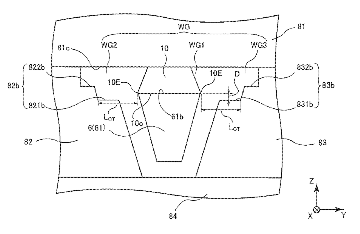
[0090]As the magnetic recording head 1, a model where the main magnetic pole layer 6 (the main magnetic pole part 61) was formed with CoFe, and the trailing shield 81, the side shields 82 and 83 and the leading shield 84 were formed with NiFe was adopted.

[0091]In the model above, a gap D between the end surfaces 82b and 83b of the side shields 82 and 83 and the end surface 10c of the spin torque oscillator 10 (the end surface 61b of the main magnetic pole part 61) along the down track direction was set at 5 nm. Simulation results are sh...

example 2

[0092]In the model above, the amplitude ΔM of the magnification of the side shields 82 and 83 was obtained by simulation in the same manner as in Example 1, except for setting the gap D between the end surfaces 82b and 83b of the side shields 82 and 83 and the end surface 10c of the spin torque oscillator 10 (the end surface 61b of the main magnetic pole part 61) along the down track direction at 10 nm (E2). Simulation results are shown in FIG. 12.

example 3

[0093]In the model above, the amplitude ΔM of the magnification of the side shields 82 and 83 was obtained by simulation in the same manner as in Example 1, except for setting the gap D between the end surfaces 82b and 83b of the side shields 82 and 83 and the end surface 10c of the spin torque oscillator 10 (the end surface 61b of the main magnetic pole part 61) along the down track direction at 20 nm (E3). Simulation results are shown in FIG. 12.


PUM

PropertyMeasurementUnit
lengthaaaaaaaaaa
thicknessaaaaaaaaaa
length LCTaaaaaaaaaa

Abstract

A magnetic recording head is provided with a main magnetic pole that generates a recording magnetic field to be applied to a magnetic recording medium from an end surface which makes a portion of an air bearing surface, a trailing shield that is placed by interposing a write gap at a trailing side of the main magnetic pole, a spin torque oscillator that is placed within the write gap to be between the main magnetic pole and the trailing shield, and two side shields that are placed at both sides of the main magnetic pole in the cross track direction, and when viewed from the air bearing surface side, at least a portion of the trailing-side end surfaces of the side shields are offset toward a leading-side of the main magnetic pole from the leading-side end surface of the spin torque oscillator.

Description

FIELD OF THE INVENTION[0001]The present invention relates to a magnetic recording head, a head gimbal assembly and a magnetic recording apparatus.BACKGROUND OF THE INVENTION[0002]In a field of magnetic recording using a head and a medium, further improvement of performance of a magnetic recording medium and a magnetic recording head is in demand in association with the high recording density of a magnetic disk device.[0003]A magnetic recording medium is a discontinuous medium where magnetic grains aggregate, and where each magnetic grain has a single magnetic domain structure. In such a magnetic recording medium, one recording bit is configured by a plurality of magnetic grains. Consequently, in order to enhance the recording density, by making the size of the magnetic grains smaller, the unevenness of the boundaries of adjacent recording bits has to be reduced. However, if the size of the magnetic nanoparticles is reduced, there is the problem that the thermal stability of magnetiz...

Claims


Application Information

Patent Timeline
Patent Type & Authority Patents(United States)
IPC IPC(8): G11B5/127G11B5/02G11B5/31G11B5/10G11B5/147G11B5/004G11B5/00
CPCG11B5/1278G11B5/3146G11B5/3133G11B5/315G11B5/10G11B5/02G11B5/147G11B5/004G11B2005/0002G11B5/235G11B5/3116G11B2005/0024
Inventor SHINOHARA, TETSUHITOROPPONGI, TETSUYADEGAWA, NAOMICHI
Owner TDK CORPARATION
Why Eureka
Try Eureka