Lens antenna system

a phased array and antenna technology, applied in the field of multi-beam phased array antenna systems, can solve the problems of substantially less power consumption of this array, and achieve the effect of improving communication and enhancing signal strength

Active Publication Date: 2018-10-30
ALL SPACE NETWORKS LTD
View PDF7 Cites 24 Cited by
  • Summary
  • Abstract
  • Description
  • Claims
  • Application Information

AI Technical Summary

Benefits of technology

[0014]The beam scanning performance of the array is controlled at two levels: coarse beam pointing and fine beam pointing. The coarse beam pointing of each lens is obtained by selecting a specific feed or small cluster of feeds excited to act as a single feed (or feed location) in the focal region of each lens. The lens and feed combination produces a directive but relatively broad beam consistent with the lens size in wavelengths and in a direction dependent on the displacement of the feed from the lens nominal focal point. By combining the corresponding feed elements in each lens of the array with appropriate phase shifts or time delays, fine control of beam pointing and high directivity due to the overall array aperture size is obtained. The set of feeds in the focal region of each lens for full electronic beam steering occupies only a fraction of the area associated with each lens so that the number of feeds and components is much lower compared with a conventional phased array. Furthermore, it is evident that, since power need be applied only to the active feeds, the power consumption of this array is substantially less than for a conventional phased array, which must have all its elements supplied with power. This specialized phased array design substantially reduces the total component count, cost, and power consumption compared with a conventional phased array with equivalent aperture size while maintaining comparable technical performance.
[0015]Furthermore, each lens and its multiple feed elements can form multiple beams simply by enabling and exciting separate feed elements in each lens with independent RF signals. Thus, the technology can be used with associated electronics for beam pointing control, and hardware and software interfaces with receive and transmit subsystems, allowing simultaneous one-way or two-way communications with one or more satellites or other remote communication nodes. The multiple beam capability along with reduced parts count and lower power consumption compared with a conventional phased array is particularly valuable in applications where it is desired to communicate with more than one satellite or, for example, to enable a “make-before-break” connection to non-geostationary satellites as they pass over the terminal.
[0016]The relatively small number of components and the flexibility afforded by having the element patterns be directive and capable of being steered over a wide range of angles offers substantial cost savings. The individually scanning antenna elements (e.g., lenses) allow for wide field of regard and, even though grating lobes exist due to the large element spacing, the degrees of freedom afforded by optimizing the element positions and orientations and the beam directions and directivity of the elements allows minimizing magnitudes of the grating lobes in the radiation pattern(s) of the array.
[0017]The array of lenses is not a sparse array, as the lenses fill the aperture area of the array. The phase center of each lens may be offset slightly, which thus breaks up the periodicity of the entire array and reduces grating lobes while having relatively low impact on efficiency, in addition to the reductions afforded by the steerable element patterns.
[0019]Furthermore, each lens can form simultaneous multiple beams by activating the appropriate feed elements. These feed elements may be combined with their own phasing or time delay networks or even with digital beam forming circuitry to form multiple high gain beams from the overall array. Design flexibility inherent in the extra degrees of freedom afforded by the lens and feed combinations along with the lens orientations and positions allows for grating lobe suppression as well as a broad field of view. The antenna system may be part of a communications terminal that includes acquisition and tracking subsystems that produce single or multiple beams covering a broad field of regard for such applications as satellite communications (Satcom) on-the-move (SOTM), 5G, broadband point-point or point-multipoint and other terrestrial or satellite communications systems. The antenna design with such lens naturally supports multiple simultaneous independently steerable beams. These simultaneous beams may be used for many applications such as: sensors for surveillance; reception of multiple transmission sources; multiple transmission beams; “make-before-break” links with non-geostationary, e.g., low earth orbit (LEO) or medium earth orbit (MEO) satellite constellations; and null placement for interference reduction without incurring the high cost of a conventional multi-beam phased array. Furthermore, the phased array antenna system can be used on spacecraft for single or multiple beam or shaped beam satellite applications.
[0021]In addition to Phased Array incarnations, MIMO (multi-input multi-output) communication systems could also make use of the capability provided by a collection lenses and associated circuitry. Although the signal processing is different for a MIMO compared to a conventional phased array, both can make use of steered beams to enhance signal strength and improve communications in a noisy or interferer-filled environment.

Problems solved by technology

Furthermore, it is evident that, since power need be applied only to the active feeds, the power consumption of this array is substantially less than for a conventional phased array, which must have all its elements supplied with power.

Method used


Image

  • Lens antenna system
  • Lens antenna system
  • Lens antenna system

Examples


Embodiment Construction

[0037]In describing the illustrative, non-limiting preferred embodiments of the invention illustrated in the drawings, specific terminology will be resorted to for the sake of clarity. However, the invention is not intended to be limited to the specific terms so selected, and it is to be understood that each specific term includes all technical equivalents that operate in similar manner to accomplish a similar purpose. Several preferred embodiments of the invention are described for illustrative purposes, it being understood that the invention may be embodied in other forms not specifically shown in the drawings.

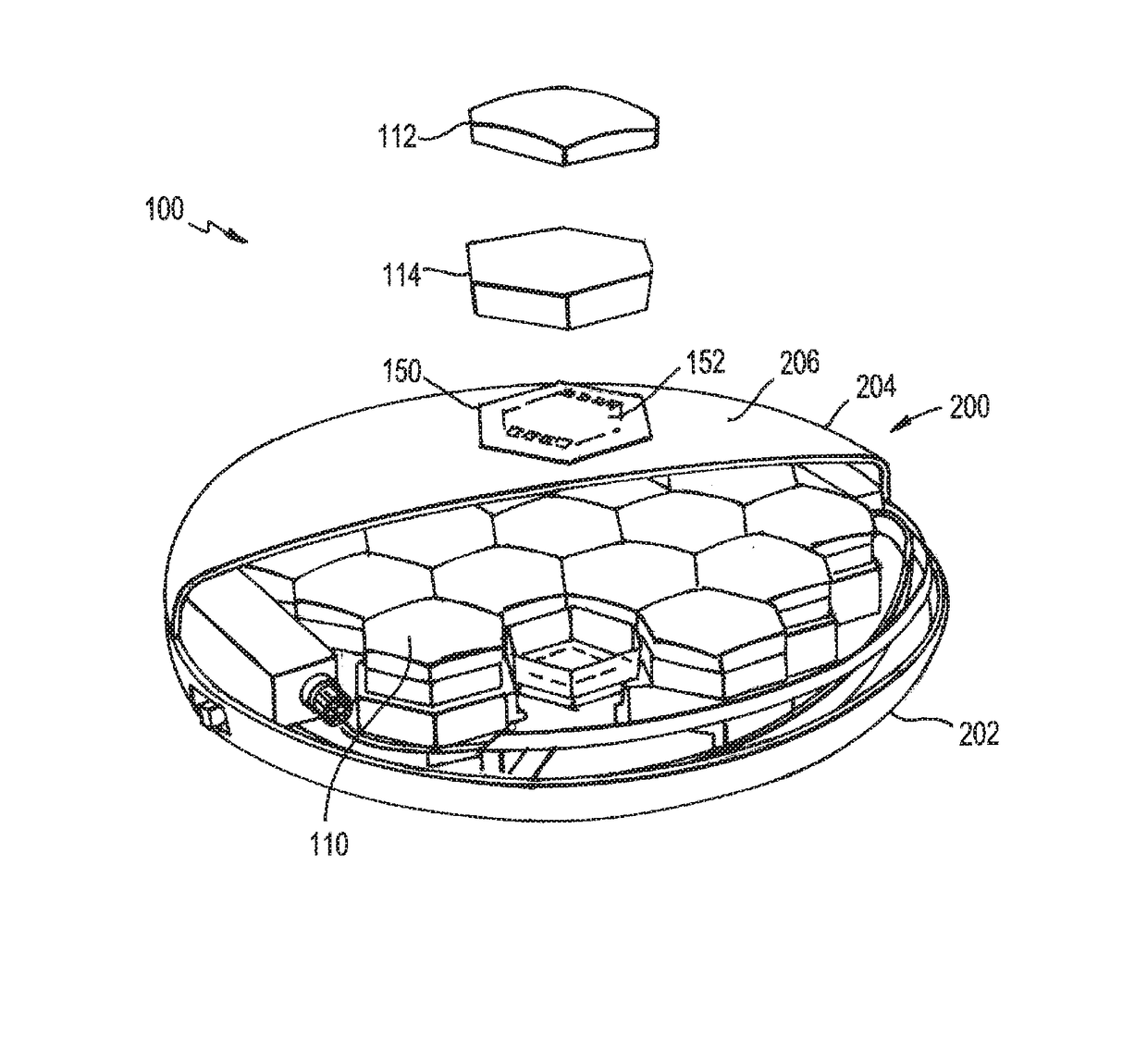
[0038]Turning to the drawings, FIG. 1 shows a lens array 100. The lens array 100 has a plurality of lens sets 110. Each lens set 110 includes a lens 112, spacer 114 and feed set 150 which has multiple feed elements 152, as shown by the one exploded lens set 110 for purposes of illustration. The spacer 114 separates the lens 112 from the feed set 150 to match the appropriate ...


PUM


Abstract

An antenna system that includes a plurality of lens sets. Each lens set includes a lens and at least one feed element. At least one feed element is aligned with the lens and configured to direct a signal through the lens at a desired direction.

Description

RELATED APPLICATIONS[0001]This application claims the benefit of U.S. Provisional Application No. 62 / 472,991, filed Mar. 17, 2017, the entire contents of which are incorporated herein by reference.BACKGROUND OF THE INVENTION[0002]Field of the Invention[0003]The present invention relates to a multiple beam phased array antenna system. More particularly, the present invention relates to a broadband wide-angle multiple beam phased array antenna system with reduced number of components using wide-angle gradient index lenses each with multiple scannable beams.[0004]Background of the Related Art[0005]Phased arrays are a form of aperture antenna for electromagnetic waves that can be constructed to be low-profile, relatively lightweight, and can steer the resulting high-directivity beam of radio energy to point in a desired direction with electrical controls and no moving parts. A conventional phased array is a collection of closely-spaced (half-wavelength) individual radiating antennas or ...

Claims


Application Information

Patent Timeline
Patent Type & Authority Patents(United States)
IPC IPC(8): H01Q3/46H01Q3/14H01Q21/22H01Q1/28H01Q21/00H01Q1/24
CPCH01Q21/22H01Q3/14H01Q3/46H01Q1/288H01Q21/0025H01Q1/241H01Q3/245H01Q3/30H01Q19/062H01Q21/061H01Q25/007
Inventor SCARBOROUGH, CLINTON P.TURPIN, JEREMIAH P.DIFONZO, DANIEL F.FINNEY, JOHN
Owner ALL SPACE NETWORKS LTD
Why Eureka
Try Eureka