Semiconductor structure and the method of making the same

a technology of semiconductors and semiconductors, applied in the direction of semiconductor devices, electrical devices, transistors, etc., can solve the problems of low resistance state, achieve high conduction speed, improve the performance of rram and transistor simultaneously, and reduce energy consumption

Active Publication Date: 2018-11-06
UNITED MICROELECTRONICS CORP
View PDF6 Cites 5 Cited by
  • Summary
  • Abstract
  • Description
  • Claims
  • Application Information

AI Technical Summary

Benefits of technology

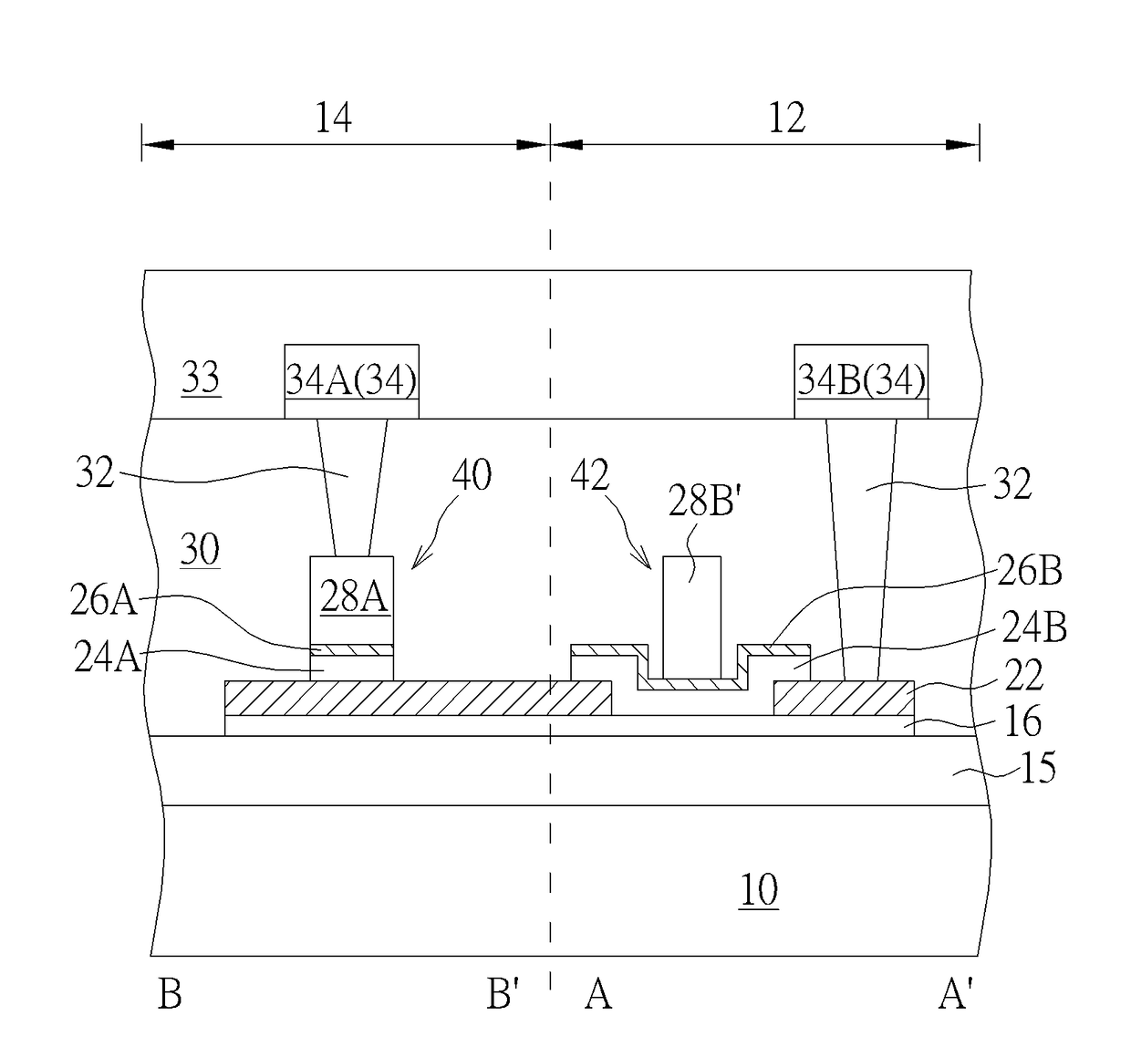
[0008]One feature of the present invention is that a 2D material layer is formed on the insulating layer, next, the RRAM and the transistor are formed on the 2D material layer respectively. Therefore, the 2D material layer may be used as a channel region of the transistor, and may also be electrically connected to the RRAM as a connection element for both devices. Besides, the 2D material layer has the advantages of high conduction speed and low energy consumption, it can improve the performance of the RRAM and the transistor simultaneously. In the present invention, some material layers can be simultaneously formed during the processes for forming the RRAM and the transistor. For example, the resistance switching layer of the RRAM and the high-k dielectric layer in the transistor are formed simultaneously by a same material layer, and the upper electrode of the RRAM and the barrier layer of the transistor are also made by one identical material layer, so that the process steps can be reduced to improve the efficiency of the process.

Problems solved by technology

Upon application of a sufficient voltage, a metallic bridge is induced to form across the data storage layer, which results in the low resistance state.

Method used


Image

  • Semiconductor structure and the method of making the same
  • Semiconductor structure and the method of making the same
  • Semiconductor structure and the method of making the same

Examples


Embodiment Construction

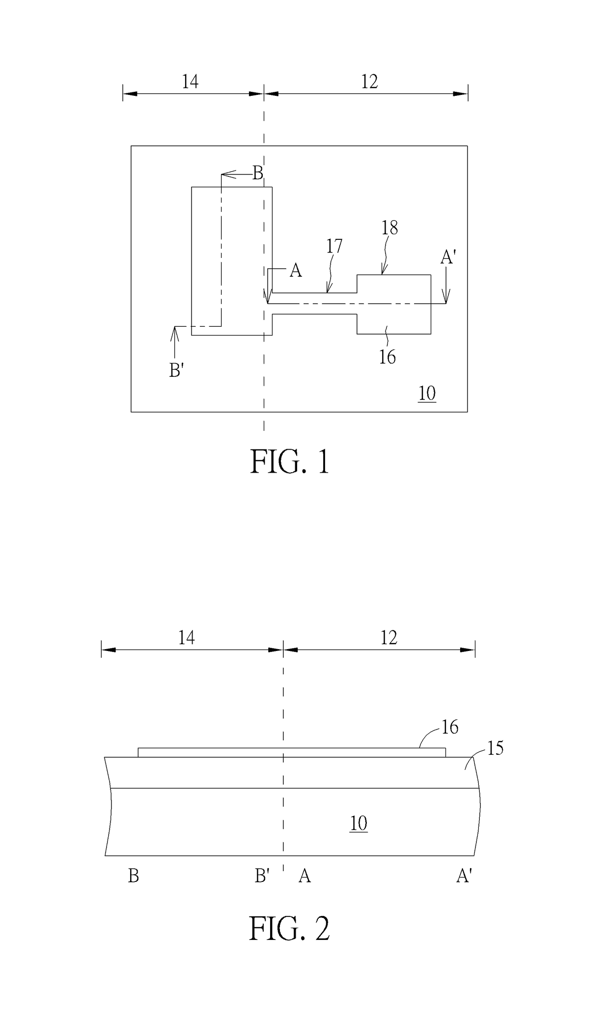
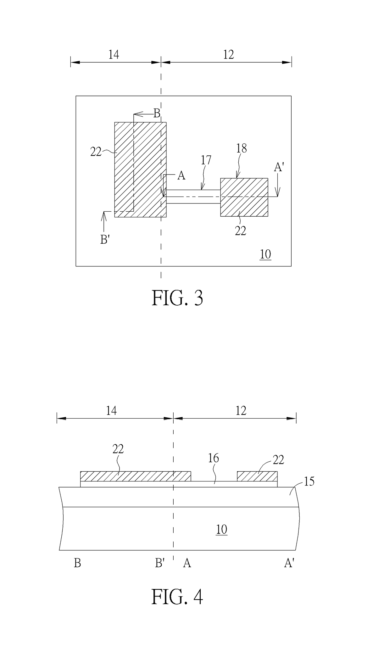
[0022]To provide a better understanding of the present invention to users skilled in the technology of the present invention, preferred embodiments are detailed as follows. The preferred embodiments of the present invention are illustrated in the accompanying drawings with numbered elements to clarify the contents and the effects to be achieved.

[0023]Please note that the figures are only for illustration and the figures may not be to scale. The scale may be further modified according to different design considerations. When referring to the words “up” or “down” that describe the relationship between components in the text, it is well known in the art and should be clearly understood that these words refer to relative positions that can be inverted to obtain a similar structure, and these structures should therefore not be precluded from the scope of the claims in the present invention.

[0024]Firstly, please refer to FIG. 1 and FIG. 2, FIG. 1 illustrates a top view diagram of a semico...


PUM


Abstract

The present invention provides a semiconductor structure, the semiconductor structure includes a substrate defining a memory region and a transistor region, an insulating layer is disposed on the substrate, a 2D material layer disposed on the insulating layer, and disposed within the memory and the transistor region, parts of the 2D material layer within the transistor region is used as the channel region of a transistor structure, the transistor structure is disposed on the channel region. And a resistive random access memory (RRAM) located in the memory region, the RRAM includes a lower electrode layer, a resistance transition layer and an upper electrode layer being sequentially located on the 2D material layer and electrically connected to the channel region.

Description

BACKGROUND OF THE INVENTION[0001]1. Field of the Invention[0002]The present invention relates to a semiconductor structure, and more particularly, to a transistor including a 2D material layer and a resistive random access memory (hereinafter abbreviated as RRAM) structure and the manufacturing method thereof.[0003]2. Description of the Prior Art[0004]Resistive random access memory (RRAM) has a simple structure, low operating voltage, high-speed, good endurance, and CMOS process compatibility. RRAM is the most promising alternative to provide a downsized replacement for traditional flash memory. RRAM is finding wide application in devices such as optical disks and non-volatile memory arrays.[0005]An RRAM cell stores data within a layer of material that can be induced to undergo a phase change. The phase change can be induced within all or part of the layer to switch between a high resistance state and a low resistance state. The resistance state can be queried and interpreted as rep...

Claims


Application Information

Patent Timeline
Patent Type & Authority Patents(United States)
IPC IPC(8): H01L27/24H01L45/00H01L29/786H01L29/49H01L29/16H01L29/24
CPCH01L27/2436H01L45/1675H01L29/1606H01L29/24H01L45/06H01L45/146H01L45/147H01L29/4908H01L29/78684H01L45/1233H10B63/30H10N70/841H10N70/011H10N70/20H10N70/8833H10N70/063H10N70/826H10N70/231H10N70/8836
Inventor LIN, CHIN-FUCHIU, CHUNG-YI
Owner UNITED MICROELECTRONICS CORP
Why Eureka
Try Eureka