Vehicle and control method therefor

a control method and technology for vehicles, applied in hybrid vehicles, electric generator control, engine starters, etc., can solve the problems of rapid lowering of accessory voltage and high probability of unstable operation of accessory devices, and achieve the effect of suppressing rapid fluctuation of accessory voltag

Active Publication Date: 2018-11-13
TOYOTA JIDOSHA KK
View PDF24 Cites 6 Cited by
  • Summary
  • Abstract
  • Description
  • Claims
  • Application Information

AI Technical Summary

Benefits of technology

[0006]An object is to provide a vehicle capable of suppressing rapid fluctuation of an accessory voltage accompanied by crank position stop control, and a control method therefor.
[0008]If the crank position stop control is executed, since a rotation speed of the rotating electric machine is rapidly lowered by the braking torque of the rotating electric machine, an output voltage of the first electric power generation device is rapidly lowered. Since the accessory voltage is constrained by an output of an electric power generation device having a higher instruction voltage out of the first and second instruction voltages, if the first instruction voltage is higher than the second instruction voltage at the time of the start of the crank position stop control, the accessory voltage is rapidly lowered from a level of the first instruction voltage to a level of the second instruction voltage. Accordingly, in this vehicle, the crank position stop control is executed in a state in which second instruction voltage is equal to or higher than the first instruction voltage. With this, since the accessory voltage is constrained by an output of the second electric power generation device at the time of the start of the crank position stop control, the accessory voltage is not lowered even if the output voltage of the first electric power generation device is rapidly lowered accompanied by the start of the crank position stop control. Therefore, according to this vehicle, it is possible to suppress fluctuation of the accessory voltage accompanied by the crank position stop control.
[0010]According to this aspect, when the first instruction voltage is higher than the second instruction voltage before executing the crank position stop control, since the relatively low second instruction voltage increases to the first instruction voltage, it is possible to suppress fluctuation of the accessory voltage accompanied by change in the second instruction voltage before executing the crank position stop control.
[0012]According to the first aspect, when the first instruction voltage is higher than the second instruction voltage before executing the crank position stop control, since the relatively high first instruction voltage decreases to be equal to or lower than the second instruction voltage at the predetermined rate, it is possible to suppress rapid fluctuation of the accessory voltage accompanied by change in the first instruction voltage before executing the crank position stop control.
[0015]In the first aspect and the second aspect, in a hybrid vehicle including an electric motor configured to produce drive power of the vehicle along with an engine, the engine repeats stop and start according to the drive power of the vehicle, charging state of the electric power storage device, or the like. These aspects are applied to such a hybrid vehicle, and in the hybrid vehicle in which the engine repeats stop and start, it is possible to suppress rapid fluctuation of the accessory voltage accompanied by the crank position stop control when the engine is stopped.
[0016]According to the first aspect and the second aspect, it is possible to provide a vehicle capable of suppressing fluctuation of the accessory voltage accompanied by the crank position stop control, and a control method therefor.

Problems solved by technology

Therefore, the accessory voltage is rapidly lowered, and an operation of an accessory is likely to become unstable.

Method used


Image

  • Vehicle and control method therefor
  • Vehicle and control method therefor
  • Vehicle and control method therefor

Examples


embodiment 1

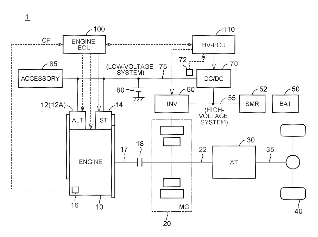
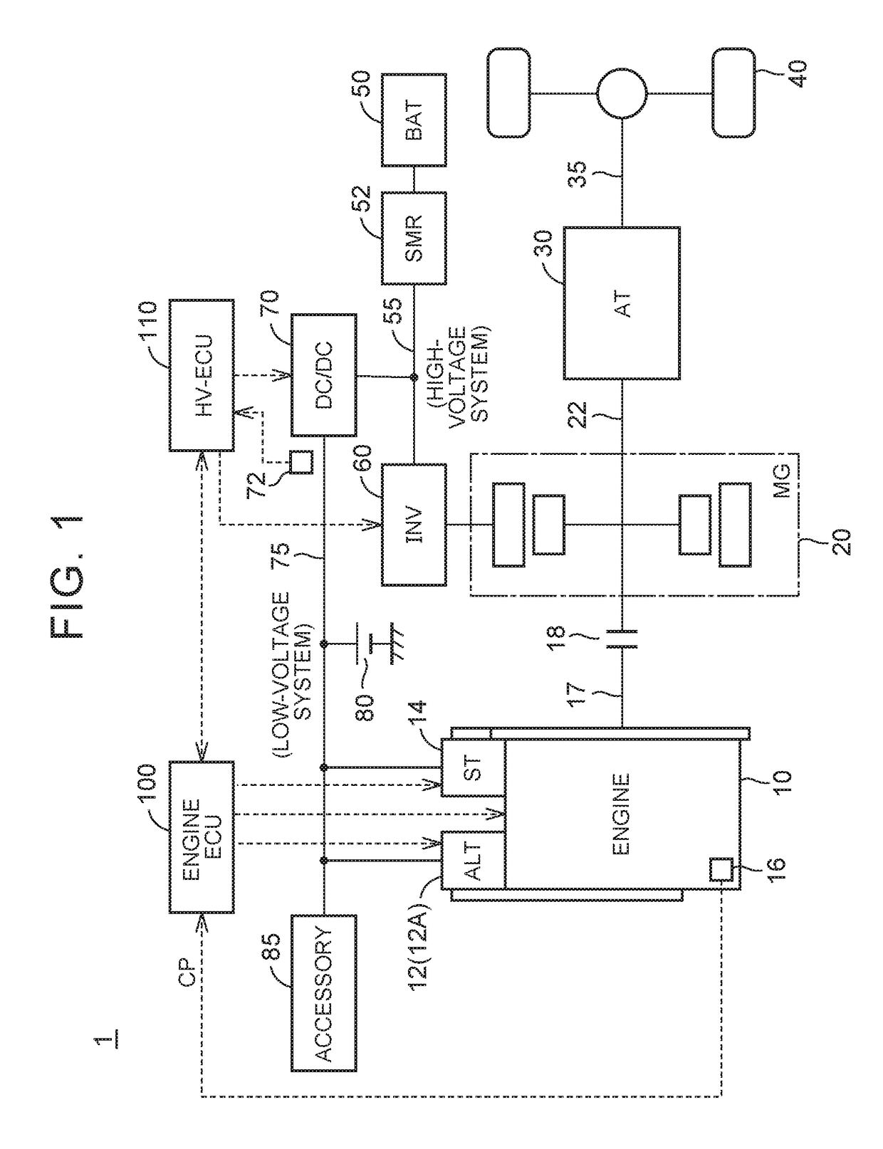
[0033]FIG. 1 is an overall configuration diagram of a vehicle according to Embodiment 1. Referring to FIG. 1, a vehicle 1 includes an engine 10, an alternator 12, a starter 14, a crank position sensor 16, a clutch 18, a motor generator (hereinafter, referred to as an “MG”) 20, an automatic transmission (hereinafter, referred to as an “AT”) 30, and drive wheels 40.

[0034]The vehicle 1 according to Embodiment 1 is a hybrid vehicle which travels using power of at least one of the engine 10 or the MG 20. A crankshaft 17 which is an output shaft of the engine 10 is connected to an input shaft (hereinafter, referred to as an “AT input shaft”) 22 of the AT 30 through the clutch 18. A rotor of the MG 20 is connected to the AT input shaft 22. An output shaft (hereinafter, referred to as an “AT output shaft”) 35 of the AT 30 is connected to the drive wheels 40 through a differential gear.

[0035]The engine 10 is an internal combustion engine, and is, for example, a gasoline engine, a diesel engi...

modification example 1

[0090]In Embodiment 1 described above, although, in a case where the stop of the engine 10 is instructed, when the instruction voltage (first instruction voltage) of the alternator 12 is higher than the instruction voltage (second instruction voltage) of the DC / DC converter 70, the second instruction voltage increases to the first instruction voltage, the first instruction voltage may be lowered to the second instruction voltage.

[0091]FIG. 8 is a diagram showing transition of an accessory voltage before and after execution of crank position stop control in a vehicle 1 according to Modification Example 1. Referring to FIG. 8, a solid line k21 indicates the voltage (accessory voltage) of the electric power line 75, and a dotted line k22 indicates the target output voltage (second instruction voltage) of the DC / DC converter 70.

[0092]Before a time t21, it is assumed that the first instruction voltage (the target output voltage of the alternator 12) is the voltage V1, and the second inst...

modification example 2

[0100]In Embodiment 1 and Modification Example 1 described above, although the crank position stop control is implemented by executing the lower arm full-phase control (FIG. 3), control for implementing the crank position stop control is not limited to the lower arm full-phase control.

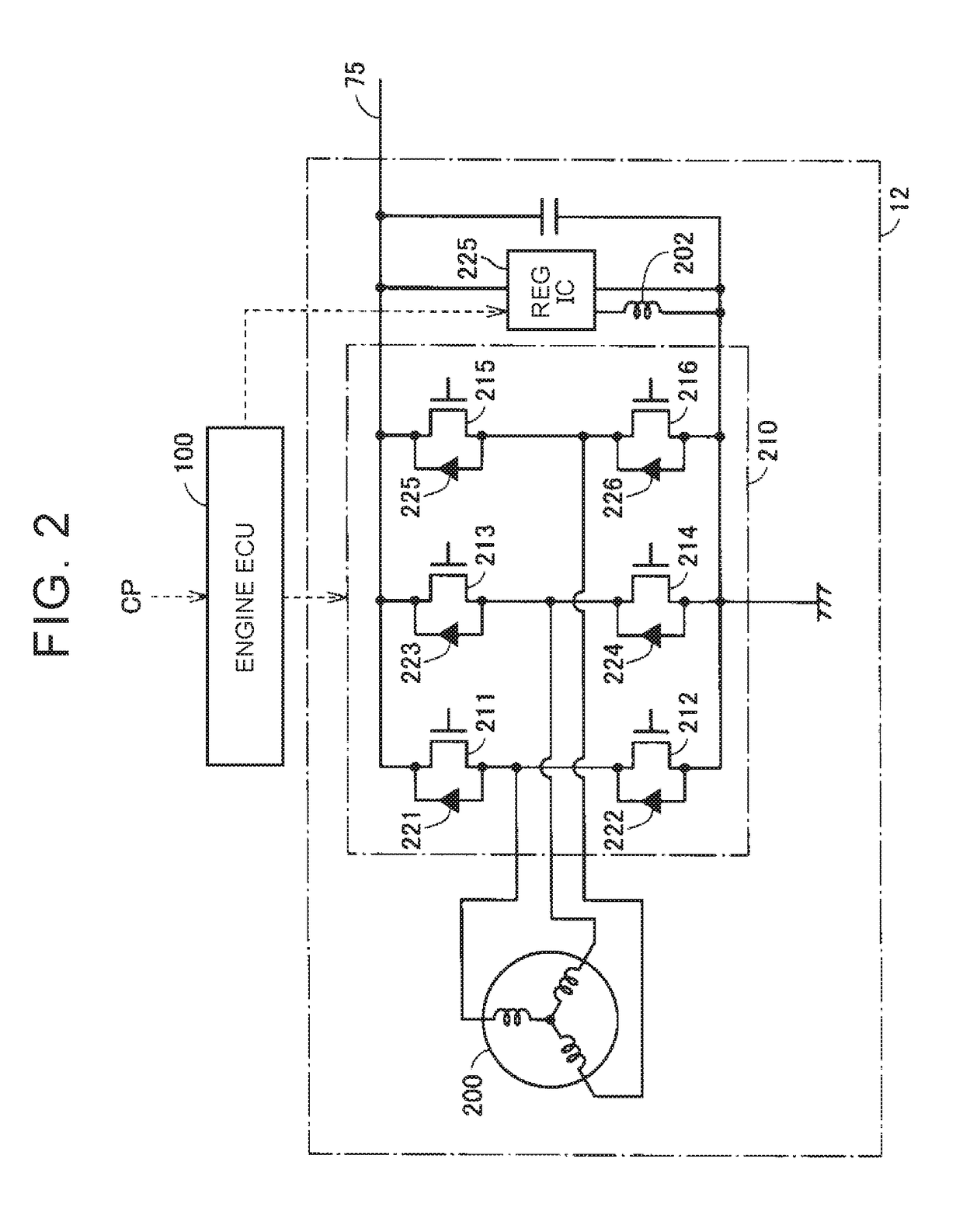
[0101]FIG. 10 is a diagram showing the configuration of an alternator in Modification Example 2. Referring to FIG. 10, an alternator 12A further includes a switching device 250 in the configuration of the alternator 12 shown in FIG. 2.

[0102]The switching device 250 includes relays 252, 254 and a resistor 256. The relay 252 is provided between the electric power line 75 and an electric power line 76 connected to the inverter 210 or the regulator IC 225. If the relay 252 is turned off (electric power shutoff), the alternator 12A is electrically disconnected from the electric power line 75. The relay 254 is connected between the electric power line 76 and a ground node. The resistor 256 is connected in se...


PUM


Abstract

A first electric power generation device configured to produce an accessory voltage according to a first instruction voltage. A second electric power generation device configured to produce the accessory voltage according to a second instruction. An electric control unit is configured to execute crank position stop control for stopping a crank of the engine at a target position when the engine is stopped by controlling the first electric power generation device such that a current is circulated in the first electric power generation device and the rotating electric machine generates braking torque. The electric control unit is configured to execute the crank position stop control in a state in which the second instruction voltage is equal to or higher than the first instruction voltage.

Description

INCORPORATION BY REFERENCE[0001]The disclosure of Japanese Patent Application No. 2016-135918 filed on Jul. 8, 2016 including the specification, drawings and abstract is incorporated herein by reference in its entirety.BACKGROUND1. Technical Field[0002]The present disclosure relates to a vehicle and a control method therefor, and in particular, a vehicle including an engine and an electric power generation device configured to receive torque from a crankshaft of the engine to produce an accessory voltage, and a control method therefor.2. Description of Related Art[0003]Japanese Patent Application Publication No. 2013-95246 (JP 2013-95246 A) discloses an electric power supply device for a vehicle including an alternator connected to an engine. The electric power supply device for a vehicle includes the alternator, a first electric power supply system having a low voltage battery, a second electric power supply system having a high voltage battery, and a DC / DC converter provided betwe...

Claims


Application Information

Patent Timeline
Patent Type & Authority Patents(United States)
IPC IPC(8): F02D29/06F02N19/00F02N11/08B60L15/20B60L11/18B60L11/14B60K6/485B60W30/18B60W10/08B60W10/06B60L1/00B60K6/46B60K6/40H02P9/04B60W20/15F02N11/04F02B63/04B60L50/16
CPCB60K6/40B60W20/15B60K6/46B60K6/485B60L1/00B60L11/14B60L11/1861B60L15/20B60W10/06B60W10/08B60W30/18018B60W30/18127F02N11/0814F02N11/0862F02N19/005Y02T10/7275Y10S903/93Y10S903/951B60L2240/441B60L2240/443B60L2240/547B60L2260/26B60W2510/30B60W2710/06B60W2710/305B60Y2200/92B60Y2300/18125B60Y2300/192B60Y2300/45B60Y2300/60B60Y2400/60F02N11/04F02N11/0866F02N2011/0885F02N2011/0888F02N2011/0896F02N2019/008Y02T10/645Y02T10/70Y02T10/7005Y02T10/705Y02T10/7044Y02T10/7077B60L50/16B60L58/12B60K2006/4825B60W20/40Y02T10/62Y02T10/64Y02T10/7072Y02T10/72
Inventor AKUZAWA, KEN
Owner TOYOTA JIDOSHA KK
Why Eureka
Try Eureka