
Dynamic packet routing

a packet routing and dynamic technology, applied in the field of dynamic packet routing, can solve the problems of inability to present mutually beneficial arrangements, inability to direct the content delivery, and technical difficulties in packet delivery performance, so as to achieve the effect of reducing costs

Active Publication Date: 2018-11-13
LEVEL 3 COMM LLC
View PDF7 Cites 0 Cited by
  • Summary
  • Abstract
  • Description
  • Claims
  • Application Information

AI Technical Summary

Benefits of technology

The patent text describes a system for routing packets in a network comprising multiple switches. The system includes a next hop determiner that determines the best path for a packet to take and a server that delivers packets to the next step. The system also has non-peering connections that transfer packets directly between the switches and the various ASes (access service providers) in the network. The technical effect of this system is that packets can be routed between the server and the ASes faster and more reliably, which is beneficial in providing high-quality services to the users.

Problems solved by technology

The content delivery may however be impeded by the lack of any direct relationship between the provider and the eyeball: The eyeball may be neither a customer nor a peer of the provider, and may be merely a customer of a third party; the third party may in turn be a customer of the provider; the provider may peer with that third party.
This may however present technical difficulties concerning packet delivery performance and / or where the third party purchases Internet connectivity from the provider and may not wish to pay for delivering the provider's traffic to the eyeball.
This may not present a mutually beneficial arrangement.
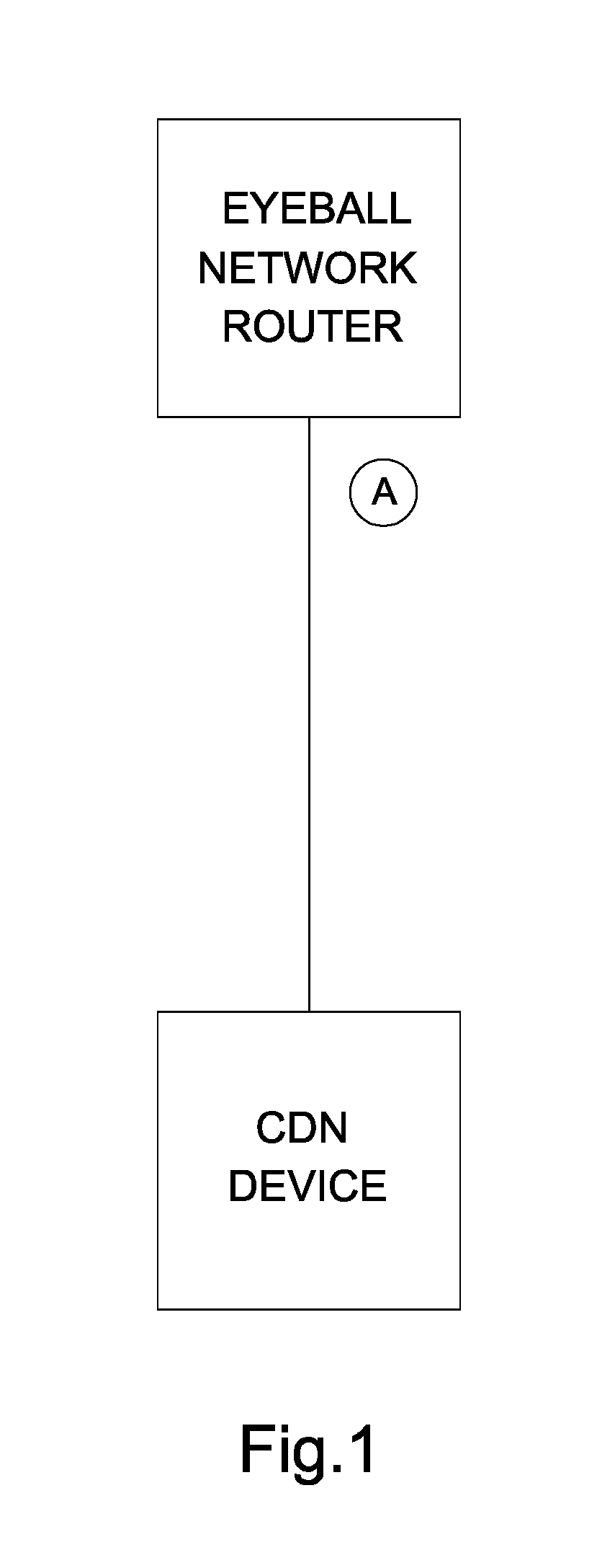
This arrangement, which may be considered to be a 1:1 multiplex situation, may represent an inefficient use of the CDN device, since the CDN server may not be able to deliver every type of content and / or may be able to deliver only to a particular eyeball.
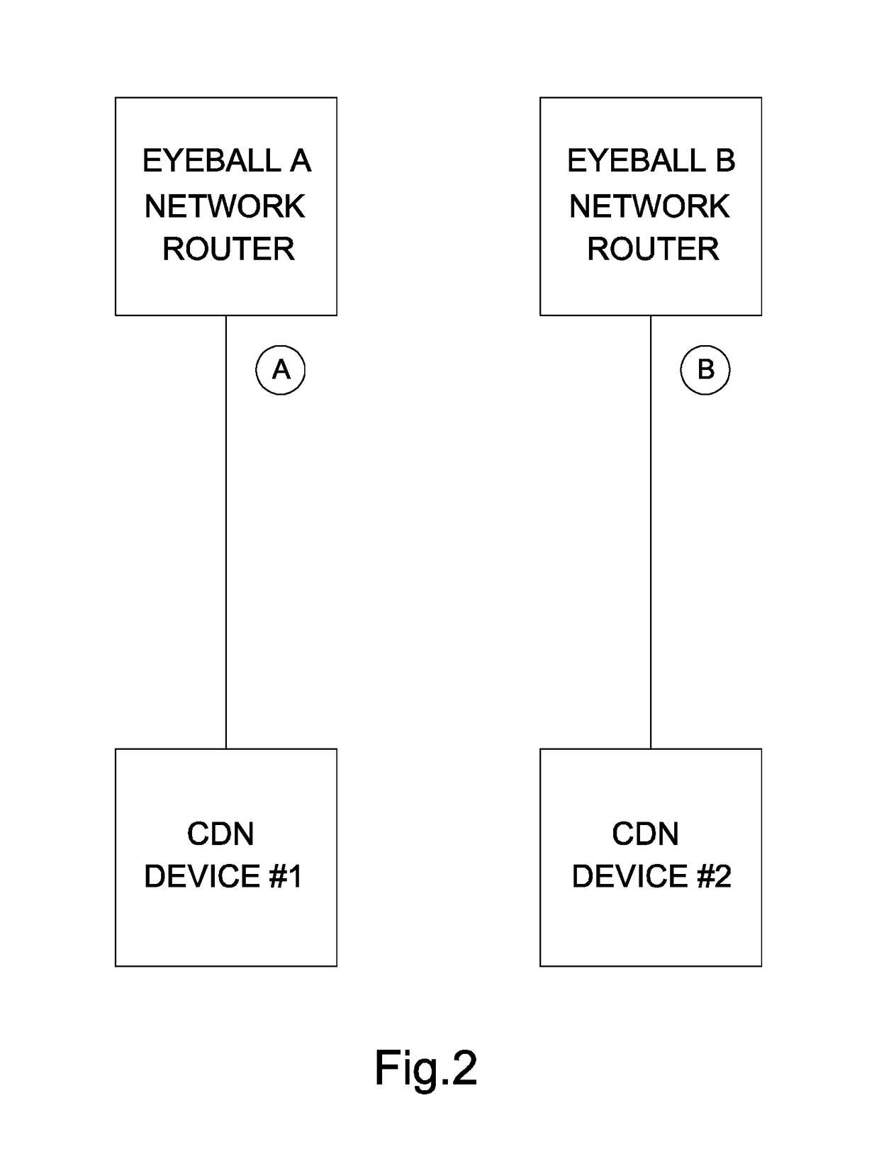
This may be considered an extension of the 1:1 multiplex situation, with similar disadvantages regarding efficiency.
The arrangements of FIGS. 1 and 2 may further be undesirable for example because they do not provide dynamic routing, for example if static links such as non-BGP are employed.

Method used


Image

  • Dynamic packet routing
  • Dynamic packet routing
  • Dynamic packet routing

Examples


Embodiment Construction

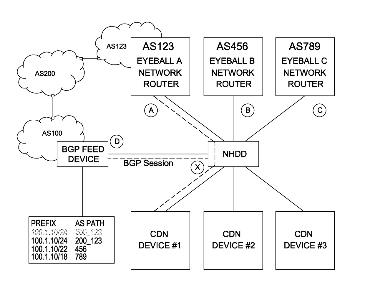
[0066]Generally, an embodiment may allow content providers, who may or may not be the operators of large IP networks, the ability to deliver dynamic content to end-user networks (generally known as eyeball networks) over private and / or public interconnects, without having for example a direct external Border Gateway Protocol (eBGP) relationship with that eyeball network over that interconnection.

[0067]Rather than such a connection using a direct, e.g., eBGP based, peering over the interconnection to enable dynamic content delivery, it may be possible to enable static routes from content provider to eyeball network. However, this does not allow for dynamic, e.g., prefix-based, delivery that comes with eBGP for example. In contrast, an embodiment of the present invention may allow dynamic, e.g., prefix-based, delivery without configuring eBGP.

[0068]Advantageously, embodiments may enable content providers to deliver content directly to eyeball networks without having to use an intermed...


PUM


Abstract

The present invention generally relates to methods of routing packets in a network comprising Autonomous Systems (ASs), next hop determiners for routing packets in such a network, systems for routing packets in such a network, and route indicator feeders for providing modified route indicators. A method of routing packets in such a network may comprise: obtaining route indicators each comprising: an indicator of a network prefix; and an indicator of an AS path for delivering packets to an AS having the network prefix; identifying at least one said route indicator having an AS path indicator comprising a predetermined AS identifier; storing the network prefix indicator of each said identified route indicator; receiving at least one packet having an address indicating a destination; and if the destination address of said packet is within an address range defined by a said stored prefix indicator, transmitting the packet on a non-peering connection to the AS having the predetermined AS identifier.

Description

CROSS REFERENCE TO RELATED APPLICATION[0001]The present application claims benefit of priority to GB Application No. 1512022.3 entitled “Dynamic Packet Routing”, filed Jul. 9, 2016, contents of which are incorporated herein by reference.FIELD OF THE INVENTION[0002]The present invention generally relates to methods of routing packets in a network comprising Autonomous Systems (ASs), next hop determiners for routing packets in a network comprising ASs, systems for routing packets in a network comprising ASs, and route indicator feeders for providing modified route indicators.BACKGROUND TO THE INVENTION[0003]The Internet can generally be described as a group of networks in the form of Autonomous Systems (AS). The ASs may belong to different owners and be connected by Border Gateway Protocol (BGP) peering; such peering may involve exchange of IP traffic based on eBGP sessions. Parties such as content and / or service providers generally mutually agree to peering and thus make public the a...

Claims


Application Information

Patent Timeline
Patent Type & Authority Patents(United States)
IPC IPC(8): H04L12/741H04L12/715H04L45/74
CPCH04L45/745H04L45/54H04L45/04
Inventor BAMFORD, STEWART
Owner LEVEL 3 COMM LLC
Learn More