Hybrid construction machine

a construction machine and hybrid technology, applied in mechanical machines/dredgers, soil shifting machines/dredgers, transportation and packaging, etc., can solve the problems of insufficient energy to be supplied to electric motors, degraded life of electricity storage devices, etc., and achieve the effect of easy recognition

Active Publication Date: 2018-12-11
NIHON KENKI CO LTD
View PDF11 Cites 0 Cited by
  • Summary
  • Abstract
  • Description
  • Claims
  • Application Information

AI Technical Summary

Benefits of technology

[0007]The present invention is made in view of the aforementioned problems in the conventional art, and an object of the present invention is to provide a hybrid construction machine that can suppress a degradation of an electricity storage device and perform a desired vehicle body movement.
[0009]Thereby, an operator can switch the mode in accordance with a load of the hydraulic actuator by the mode selection device. For example, since it is possible to lower the target electricity storage rate at a light load, the electricity storage device repeatedly performs the charge / discharge in a state of a low electricity storage rate to suppress the degradation of the electricity storage device, making it possible to extend the lifetime of the electricity storage device. On the other hand, at the time of performing a successive heavy load work as much as to surpass the charge of the electricity storage device, it is possible to increase the target electricity storage rate. Therefore, it is possible to perform the movement of the vehicle body in accordance with a demand of the operator for a long period.
[0011]Thereby, the charge can catch up by an amount by which a discharge energy amount of the electricity storage device becomes small at working. As a result, it is possible to perform the vehicle body movement by a low target electricity storage rate as a result of priority of the lifetime in the electricity storage device with no concern about a reduction in electricity storage rate.
[0012](3) According to the present invention, the controller continuously and gradually changes a value of the target electricity storage rate from a value before mode change to a value after mode change when the mode is changed by the mode selection device. Thereby, since it is possible to gradually change the electricity storage rate at the mode change, it is possible to prevent an abrupt change in electricity storage rate to prevent an unexpected vehicle body movement.
[0014](5) According to the present invention, the mode selection device does not limit the maximum power of the hydraulic pump and can select a maximum electricity storage rate mode in which the target electricity storage rate is set in the vicinity of the maximum electricity storage rate of the electricity storage device. Thereby, by selecting the maximum electricity storage rate mode, even when work continuity is top-prioritized, for example, as at the climbing travel and the like, the vehicle body movement can continue for a possible long time.
[0015](6) The present invention further comprising: an in-vehicle monitor that displays the mode selected by the mode selection device. Thereby, an operator can easily recognize the mode selected at present by visual contact with the in-vehicle monitor.

Problems solved by technology

However, in the method according to Patent Document 1, since the degradation of the electricity storage device due to repetition of the charge / discharge is not considered, there is a possibility that the lifetime of the electricity storage device degrades.
However, when the target electricity storage amount of the electricity storage device is always set to a low value, for example, in a case where a heavy load work continues, energy to be supplied to the electric motor becomes insufficient, possibly causing a problem with an operation of the working mechanism or the like.

Method used


Image

  • Hybrid construction machine
  • Hybrid construction machine
  • Hybrid construction machine

Examples


Embodiment Construction

[0026]Hereinafter, a hybrid hydraulic excavator as a hybrid construction machine according to an embodiment in the present invention will be explained as an example with reference to the accompanying drawings.

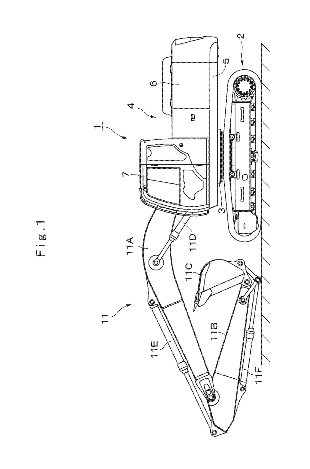
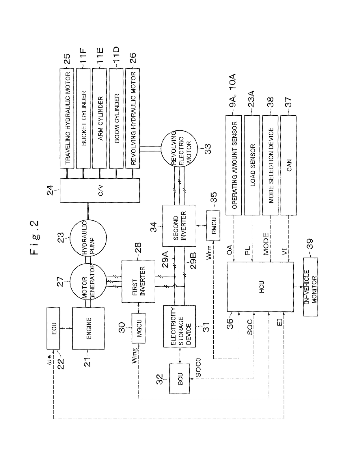
[0027]FIG. 1 to FIG. 9 show an embodiment of the present invention. In FIG. 1, a hybrid hydraulic excavator 1 (hereinafter, referred to as “hydraulic excavator 1”) is provided with an engine 21 and a motor generator 27 to be described later. The hydraulic excavator 1 includes an automotive lower traveling structure 2 of a crawler type, a revolving device 3 that is provided on the lower traveling structure 2, an upper revolving structure 4 that is rotatably mounted on the lower traveling structure 2 through the revolving device 3, and a working mechanism 11 that is provided in the front side of the upper revolving structure 4 and performs an excavating operation of earth and sand and the like. At this time, the lower traveling structure 2 and the upper revolving structure 4 conf...


PUM


Abstract

A motor generator (27) is connected mechanically to an engine (21) and a hydraulic pump (23). The hydraulic pump (23) delivers pressurized oil to cylinders (11D) to (11F) in a working mechanism (11), a traveling hydraulic motor (25) and a revolving hydraulic motor (26). The revolving hydraulic motor (26) drives a revolving device (3) in cooperation with a revolving electric motor (33). The motor generator (27) and the revolving electric motor (33) are connected electrically to an electricity storage device (31). An HCU (36) sets a target electricity storage rate (SOC0) of the electricity storage device (31) and a pump output limit (POL0) of the hydraulic pump (23) corresponding to a mode selected by a mode selection device (38). The HCU (36) controls the engine (21), the motor generator (27), the revolving electric motor (33) and the electricity storage device (31) corresponding to the target electricity storage rate (SOC0) and the pump output limit (POL0).

Description

TECHNICAL FIELD[0001]The present invention relates to a hybrid construction machine on which an engine and a motor generator are mounted.BACKGROUND ART[0002]In general, there is known a hybrid construction machine provided with a motor generator that is jointed mechanically to an engine and a hydraulic pump, and an electricity storage device such as an lithium ion battery or capacitor and the like (for example, refer to Patent Document 1). In this hybrid construction machine, the motor generator has a function of charging power generated by a driving force of the engine in the electricity storage device or assisting in the engine by power running which uses power of the electricity storage device. Many hybrid construction machines are provided with an electric motor separated from the motor generator, and the electric motor acts for or assists in an operation of a hydraulic actuator. For example, at the time of performing a revolving operation by the electric motor, the electric mot...

Claims


Application Information

Patent Timeline
Patent Type & Authority Patents(United States)
IPC IPC(8): B60W20/13E02F9/12E02F9/20E02F9/22E02F3/32
CPCB60W20/13E02F9/123E02F9/2075E02F9/2091E02F9/2095E02F9/2296E02F3/32E02F9/2246E02F9/2271E02F9/26
Inventor HITA, MASAFUMIISHIDA, SEIJITAKEUCHI, KENIMURA, SHINYA
Owner NIHON KENKI CO LTD
Why Eureka
Try Eureka