Eureka AIR delivers breakthrough ideas for toughest innovation challenges, trusted by R&D personnel around the world.

Stereoscopic three dimensional projection system using elliptical polarization

Inactive Publication Date: 2018-12-11
VOLFONI R&D
View PDF12 Cites 1 Cited by
  • Summary
  • Abstract
  • Description
  • Claims
  • Application Information

AI Technical Summary

Benefits of technology

The present invention is a type of stereoscopic 3D projection system that uses elliptical polarization, which allows it to operate at higher frame-rates than other systems that use circular polarization. It also has improved optical light efficiency due to the use of a reduced dark-time period for the projector. The system can use liquid crystal elements with lower viscosity and a lower anisotropic index of refraction, which allows them to switch faster than elements designed for circular polarization. Overall, this results in a more efficient and faster stereoscopic 3D projection system.

Problems solved by technology

Moreover, since the switching speed of said liquid crystal elements is directly related to said product of anisotropic index of refraction (Δn) and cell-gap (d), this therefore limits the maximum speed at which said liquid crystal elements are able to switch between said first and second optical states thereof.
In practice, the maximum switching speed of pi-cell liquid crystal elements designed to generate circular polarization when operating together with visible light is typically only approximately 250 μs, and this relatively slow speed therefore limits both the maximum frame-rate at which said pi-cell liquid crystal elements are able to operate, as well as limiting the maximum optical light efficiency that can be achieved due to the necessity of utilizing a relatively long dark-time period for the projector.
This will therefore also significantly reduce the overall optical light efficiency of the aforementioned system, thereby resulting in the creation of time-multiplexed stereoscopic 3d images according to the state-of-the-art that are severely lacking in on-screen image brightness.
This therefore once again limits the minimum permissible value for said product of anisotropic index of refraction (Δn) and cell-gap (d) for said liquid crystal elements thereof, thereby also limiting the maximum switching speed that can be achieved by said liquid crystal elements according to the state-of-the-art.
This results in there being a limitation on both the maximum frame-rate as well as the maximum optical light efficiency that can be achieved by said stereoscopic 3d projection system that is based on circular polarization according to the prior-art.
The double image-beam system described above according to the state-of-the-art also has the disadvantage in that there is a relatively large optical path-length difference between said primary and secondary image-beams thereof, thereby typically requiring the use of a telephoto-lens pair and / or the deformation of said reflecting-surface in order to compensate for said optical path-length difference.
However, this adds both complexity and expense to the overall system.
This in turn limits both the maximum frame-rate and the maximum optical light efficiency that can be achieved by said liquid crystal elements thereof, hence limiting the overall performance of said time-multiplexed stereoscopic 3d projection system according to the state-of-the-art.

Method used


Image

  • Stereoscopic three dimensional projection system using elliptical polarization
  • Stereoscopic three dimensional projection system using elliptical polarization
  • Stereoscopic three dimensional projection system using elliptical polarization

Examples


Embodiment Construction

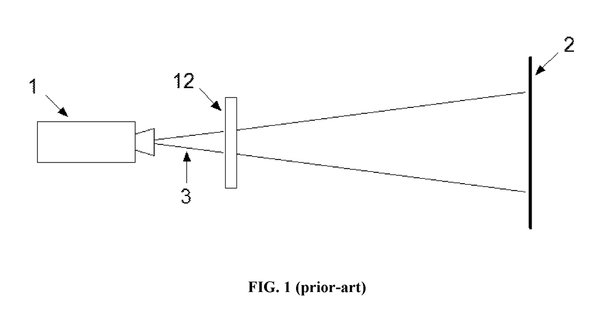
[0033]FIG. 1 shows a stereoscopic 3d projection system based on a single image-beam architecture according to the state-of-the-art where a polarization modulator 12 comprising a stack of one or more liquid crystal elements (not shown) is placed directly in-front of the lens of a projector 1, such as a 3-chip DLP digital cinema projector or otherwise.

[0034]The projector 1 generates an incident image-beam 3 comprising a succession of alternate left and right-eye images at high frequency of typically 144 Hz and said polarization modulator 12 is arranged so as to impart a first circular polarization state to all left-eye images and a second circular polarization state to all right-eye images, with said first and second circular polarization states being mutually orthogonal.

[0035]Thereafter, said left and right-eye images are focused onto the surface of a polarization-preserving projection-screen 2 such as a silver-screen or otherwise, thereby enabling the viewing of time-multiplexed ste...


PUM


Abstract

The present invention discloses a stereoscopic 3d projection system that is based on elliptical polarization, and more specifically a time-multiplexed stereoscopic 3d projection system that enables the viewer to observe stereoscopic 3d images on the surface of a polarization-preserving projection-screen via utilization of passive elliptically-polarized viewing-glasses. The disclosed invention provides a stereoscopic 3d projection system that is capable of operating at higher frame-rates and / or with higher optical light efficiency as compared to other prior-art technologies that are instead based on circular polarization.

Description

CROSS-REFERENCE TO RELATED APPLICATION[0001]This application claims the benefit of priority to U.S. Provisional Application No. 62 / 553,518, filed Sep. 1, 2017, which is incorporated herein by reference.FIELD OF INVENTION[0002]The present invention relates to a stereoscopic three dimensional (3d) projection system based on elliptical polarization, and more specifically to a stereoscopic 3d projection system for the viewing of time-multiplexed stereoscopic 3d images via utilization of passive, elliptically-polarized viewing-glasses. The disclosed invention enables the viewing of stereoscopic 3d images at higher frame-rates and / or with higher optical light efficiency as compared to other prior-art technologies that instead use circular polarization according to the state-of-the-art.BACKGROUND OF THE INVENTION[0003]Stereoscopic three dimensional (3d) projection systems have been used for many years. One technology known to the art and described, for example, in U.S. Pat. No. 7,528,906 B...

Claims


Application Information

Patent Timeline
IPC IPC(8): G02B27/26G02B27/22G03B35/16G02B27/14G03B21/28G02F1/139G02F1/1347G02B30/25
CPCG02B27/26G03B35/16G02B27/2264G02F1/13471G03B21/28G02F1/1395G02B27/144H04N13/337H04N13/341H04N13/363G03B35/26G02B30/25G02B30/24
Inventor PALMER, STEPHEN
Owner VOLFONI R&D
Why Eureka
Eureka Blog
Learn More