Movable divided inspection system and method

a divided inspection system and moving technology, applied in the field of scanning inspection, can solve the problems of difficult to find a fixed area to achieve the passage of all agv equipment, the corresponding limitations of the mobile gantry category, and the inability to adapt to the demands of current intelligent ports, so as to achieve the effect of more flexibly and conveniently performing inspection of an articl

Active Publication Date: 2018-12-18
NUCTECH CO LTD
View PDF15 Cites 0 Cited by
  • Summary
  • Abstract
  • Description
  • Claims
  • Application Information

AI Technical Summary

Benefits of technology

[0008]It is an object of the present invention to provide a movable divided inspection system and method, so as to more flexibly and conveniently perform inspection of an article to be scanned.
[0040]According to the aforementioned technical solution, the present invention drives movement of the first radiation source and the first detection means by the automated guided vehicle, by mounting both the first radiation source and the first detection means on the automated guided vehicle, so that the first radiation source and the first detection means are also relatively flexible in movement, and not necessarily limited by a site, since the automated guided vehicle is relatively flexible in movement; moreover, the first radiation source and the first detection means are respectively mounted on different automated guided vehicles, i.e. the scanning inspection system which is of a divided structure presents better flexibility and adaptability; for intelligent ports that have already been implemented and accomplished in planning, it is possible to utilize a track available on the site so that there is no need for secondary civil engineering, and there is also no need for occupying a fixed area; compared to an inspection system of a vehicle mounted category, there is also not present with a limit in aspects such as emission of the chassis vehicle as well as relevant road regulations.

Problems solved by technology

In the above container inspection systems of a vehicle mounted category and a mobile gantry category, the vehicle mounted category may be limited by emission of the chassis vehicle, left rubber / right rudder as well as other relevant road regulations, while the mobile gantry category is correspondingly limited with a need for use at a fixed site.
A movable container inspection as a link of a port makes it necessary for centralized management and control, and makes it necessary for effectuating unattended operation on an inspection system, but regardless of a vehicle mounted category and a mobile gantry category, such two movement manners are both hard to adapt to the demands of current intelligent ports.
At the same time, magnetic nails of an equipment that guides an AGV are throughout the entire AGV advancing site, it is rather difficult for secondary civil engineering on the basis of the container inspection system, and moreover, it is also hard to find a fixed area to achieve passage of all AGV equipment.
Thus, the existing inspection system of a fixed gantry category cannot adapt to the demands of current intelligent ports as well.

Method used


Image

  • Movable divided inspection system and method
  • Movable divided inspection system and method

Examples


first embodiment

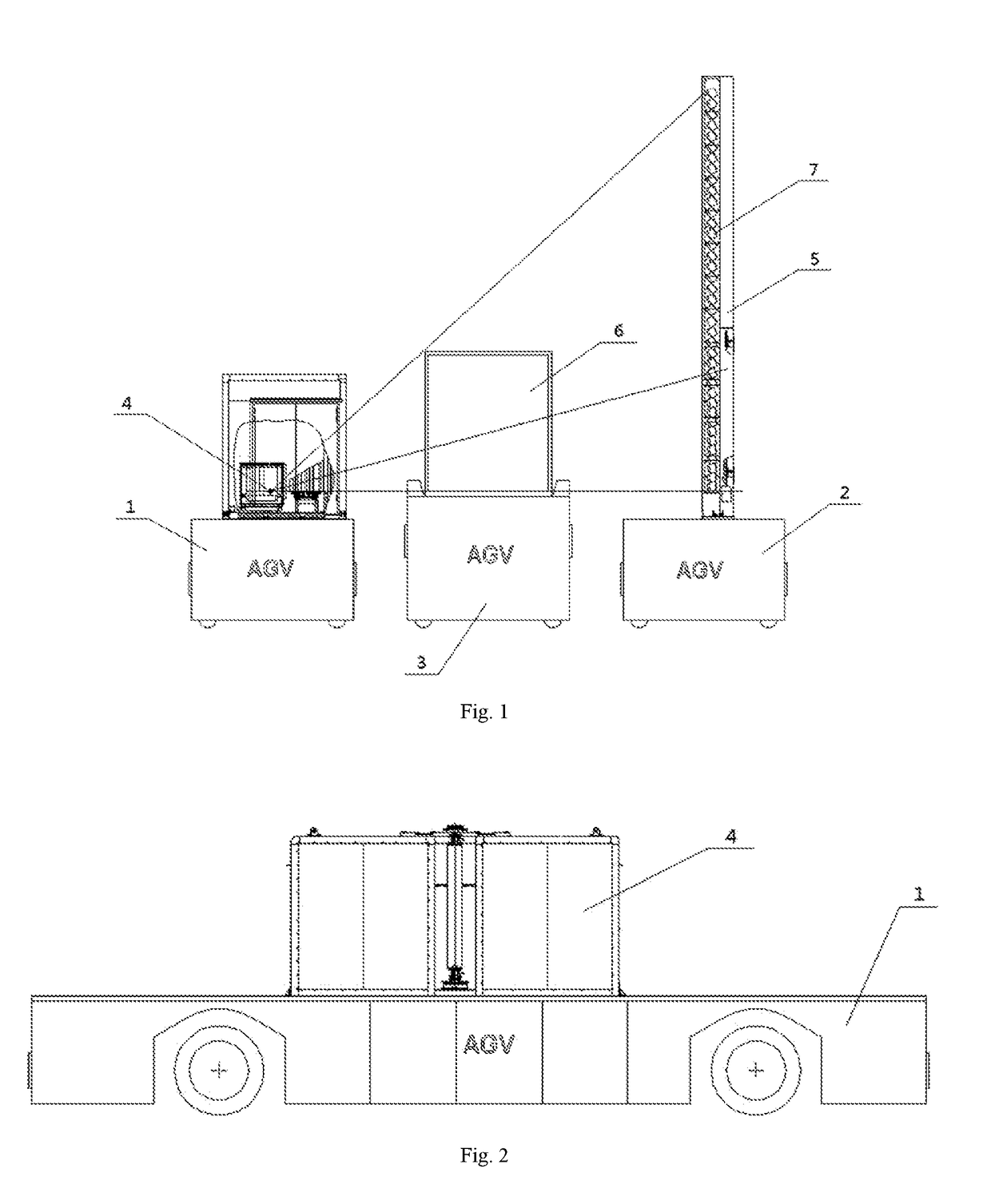
[0069]In the first embodiment, the position adjustment means includes a second detector disposed on the detector arm, a direction in which the second detector is arranged and the axis of the detector arm 5 being perpendicular to each other, so as to adjust relative position relationship of the first radiation source 4 and the detector arm 5 by a radiation dose received by the second detector. The second detector comprises one or more, each the second detector is provided with a plurality of detecting pens, preferably, the setting direction of the plurality of detecting pens is perpendicular to the axis of the detector arm 5.

[0070]As the direction in which the second detector is arranged and the detector 5 may be perpendicular to each other, for example when it is necessary to adjust the relative position relationship of the first radiation source 4 and the detector arm 5 in the front-and-rear direction, the second detector may be arranged along the front-and-rear direction, so that ...

second embodiment

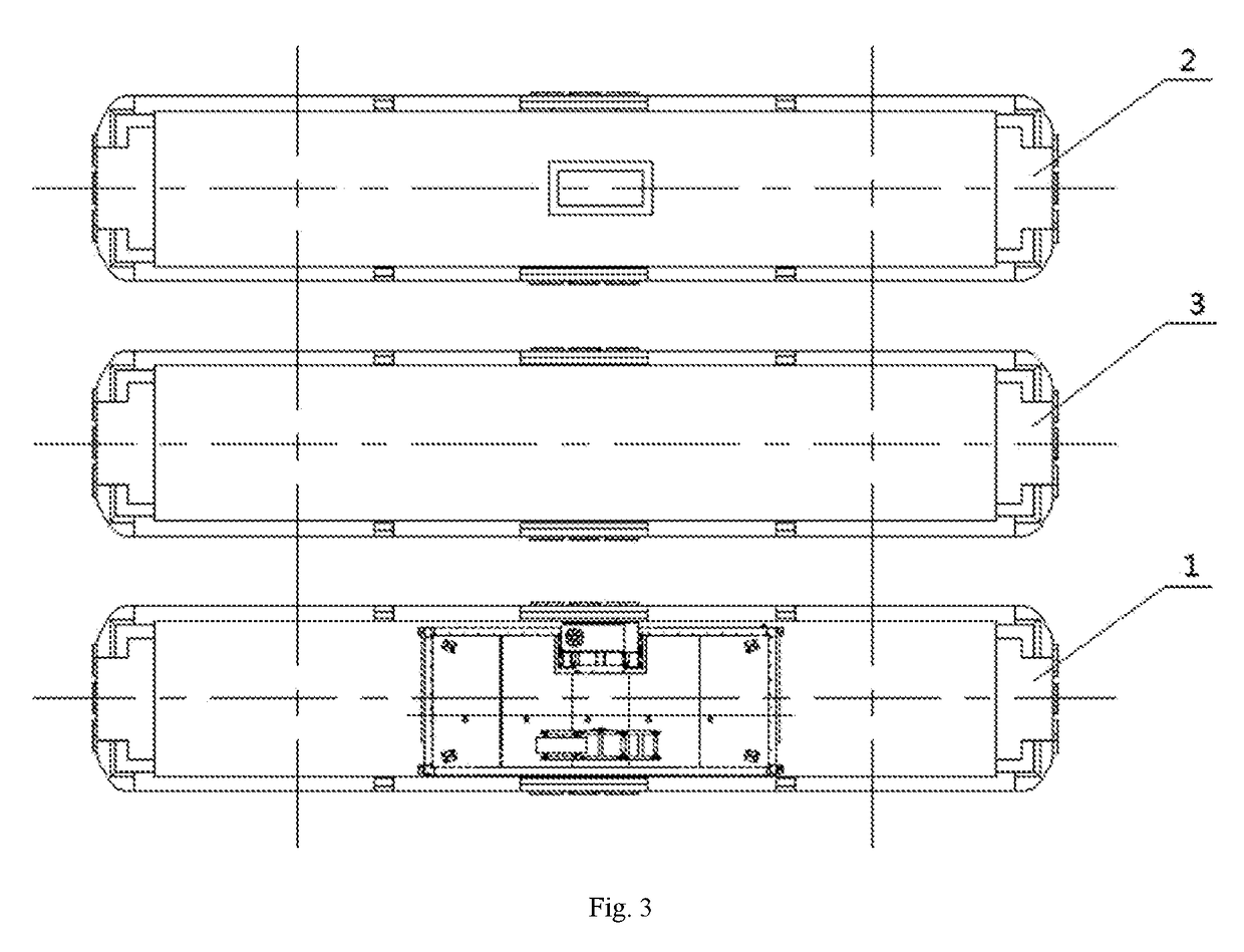
[0073]In the second embodiment, the position adjustment means includes a laser plane meter provided on the first automated guided vehicle and a laser receiver provided on the second automated guided vehicle 2, to adjust a position of the laser receiver relative to the first automated guided vehicle 1 according to a laser plane emitted by the laser plane meter, so as to adjust relative position relationship of the detector arm 5 and the first radiation source 4.

[0074]In the embodiment, since the position of the laser plane meter relative to the first radiation source 4 may be acquired in advance, the position of the laser receiver relative to the detector arm 5 may also be acquired in advance, so that the relative position relationship of the detector arm 5 and the first radiation source 4 may be determined after the relative position relationship of the laser receiver and the laser plane meter are determined.

[0075]In the embodiment, it may be made that the laser plane meter is provi...


PUM

PropertyMeasurementUnit
lengthaaaaaaaaaa
angleaaaaaaaaaa
movementaaaaaaaaaa

Abstract

This invention relates to a movable divided inspection system and method, wherein the scanning inspection system comprises a first radiation source, a first detection means, a first automated guided vehicle and a second automated guided vehicle. The first radiation source is mounted on the first automated guided vehicle. The first detection means is mounted on the second automated guided vehicle. The first automated guided vehicle and the second automated guided vehicle are able to drive the first radiation source and the first detection means to a preset scan inspection position, so as to form a scanning passage for passage of an article to be scanned between the first and second automated guided vehicle, such that scanning inspection of said article to be scanned is realized by relative movement of said article to be scanned with reference to said first automated guided vehicle and said second automated guided vehicle.

Description

CROSS REFERENCE TO RELATED APPLICATION[0001]The present application claims the priority to Chinese Patent Application No. 201610786651.7, titled “MOVABLE DIVIDED INSPECTION SYSTEM AND METHOD”, filed on Aug. 31, 2016 with the State Intellectual Property Office of the PRC, which is incorporated herein by reference in its entirety.FIELD OF THE INVENTION[0002]The present invention relates to the technical field of scanning inspection, and in particular relates to a movable divided inspection system and method.BACKGROUND OF THE INVENTION[0003]The existing container inspection system is commonly in such categories as a fixed gantry category, a mobile gantry category and a vehicle mounted category. Among them, the container inspection system of a fixed gantry category, is in such an inspection manner that a gantry is fixed on a scanning passage, while an article to be inspected passes through a scanning passage to accomplish the scanning; a mobile gantry category and a vehicle mounted cate...

Claims


Application Information

Patent Timeline
Patent Type & Authority Patents(United States)
IPC IPC(8): G01F23/00G01V5/00G05D1/00G01N23/04
CPCG01N23/04G05D1/0094G01V5/0066G05D2201/0207G01V5/0016
Inventor CHEN, ZHIQIANGLI, YUANJINGSUN, SHANGMINHU, YUMA, YUANWANG, QIANGQIANGDU, LONGLI, WEI
Owner NUCTECH CO LTD
Why Eureka
Try Eureka