Large area magnetic flux sensor

a magnetic flux and large-area technology, applied in the field of magnetic flux sensors, can solve the problems of piezoelectric voltage dissipation, device disclosed by chen is not capable of continuously measuring static or slowly varying magnetic flux, and no practical method to measure total static, etc., to achieve high sensitivity, noise immunity, and dynamic range

Active Publication Date: 2019-01-08
THE UNITED STATES OF AMERICA AS REPRESENTED BY THE SECRETARY OF THE NAVY
View PDF8 Cites 10 Cited by
  • Summary
  • Abstract
  • Description
  • Claims
  • Application Information

AI Technical Summary

Benefits of technology

[0022]The magnetic flux sensor of the present invention may include one or more additional features to ensure high sensitivity, dynamic range, and noise immunity. By way of example, one, some, or all of the following features are possible in inventive practice: The piezoelectric areas may be shielded by conductive bars in close proximity to prevent contamination by the electromagnetic fields from the current conducting area or from other sources. There may be an enclosing conductive case that forms another layer of shielding. There may be a magnetically transparent window covering the conducting area to protect it and prevent impingement of air currents. There may be a mass-spring suspension system to isolate the sensing sheet from mechanical vibration. All cabling may be shielded to prevent induced electromagnetic noise.

Problems solved by technology

There currently exists no practical method to measure the total static and dynamic magnetic flux passing normally through a large area.
Semiconductor Hall devices are commonly used in magnetic machines, but they are small and essentially sample a single point.
Magnetoresistive devices are becoming more practical; however, they are small and they sense flux down the device axis and not though the sensor thickness.
It should be appreciated that the device disclosed by Chen is not capable of continuously measuring a static or slowly varying magnetic flux.
A statically induced piezoelectric voltage will dissipate with time, and stray electrical charge noise will build up in the detection circuit and degrade the flux measurement accuracy of Chen's device.
Also, the construction methods of the apparatus disclosed by Chen limits its use to a small area.

Method used


Image

  • Large area magnetic flux sensor
  • Large area magnetic flux sensor
  • Large area magnetic flux sensor

Examples


Embodiment Construction

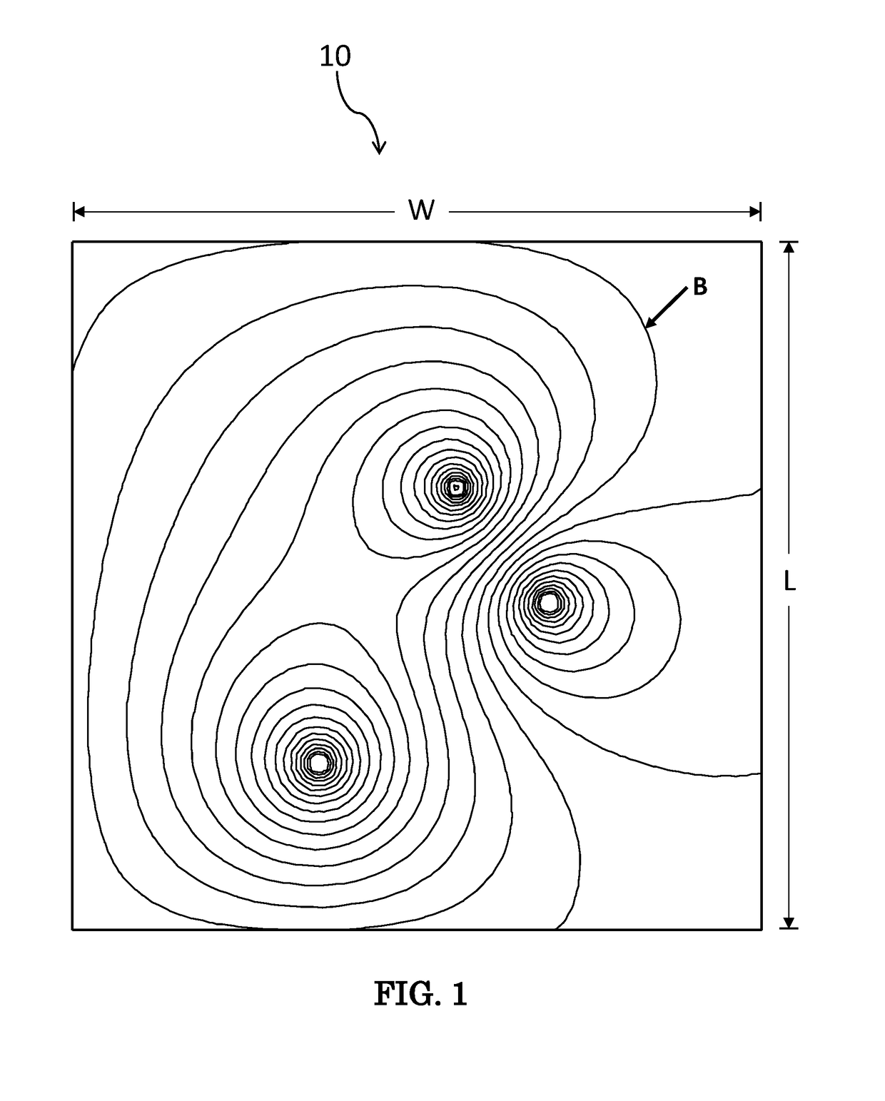
[0030]Referring now to FIG. 1, shown is an exemplary area of interest 10, characterized by width W and length L. Magnetic flux passes through this area 10, and exemplary magnetic flux density contours are shown as lines labeled B. The total normal magnetic flux Φ is equal to B integrated over the area 10. There is no known method or device to quickly and accurately measure the total normal magnetic flux Φ passing through example area 10. Conventional sensors, such as Hall sensors, would require numerous point measurements to obtain enough data to accurately integrate B over the area.

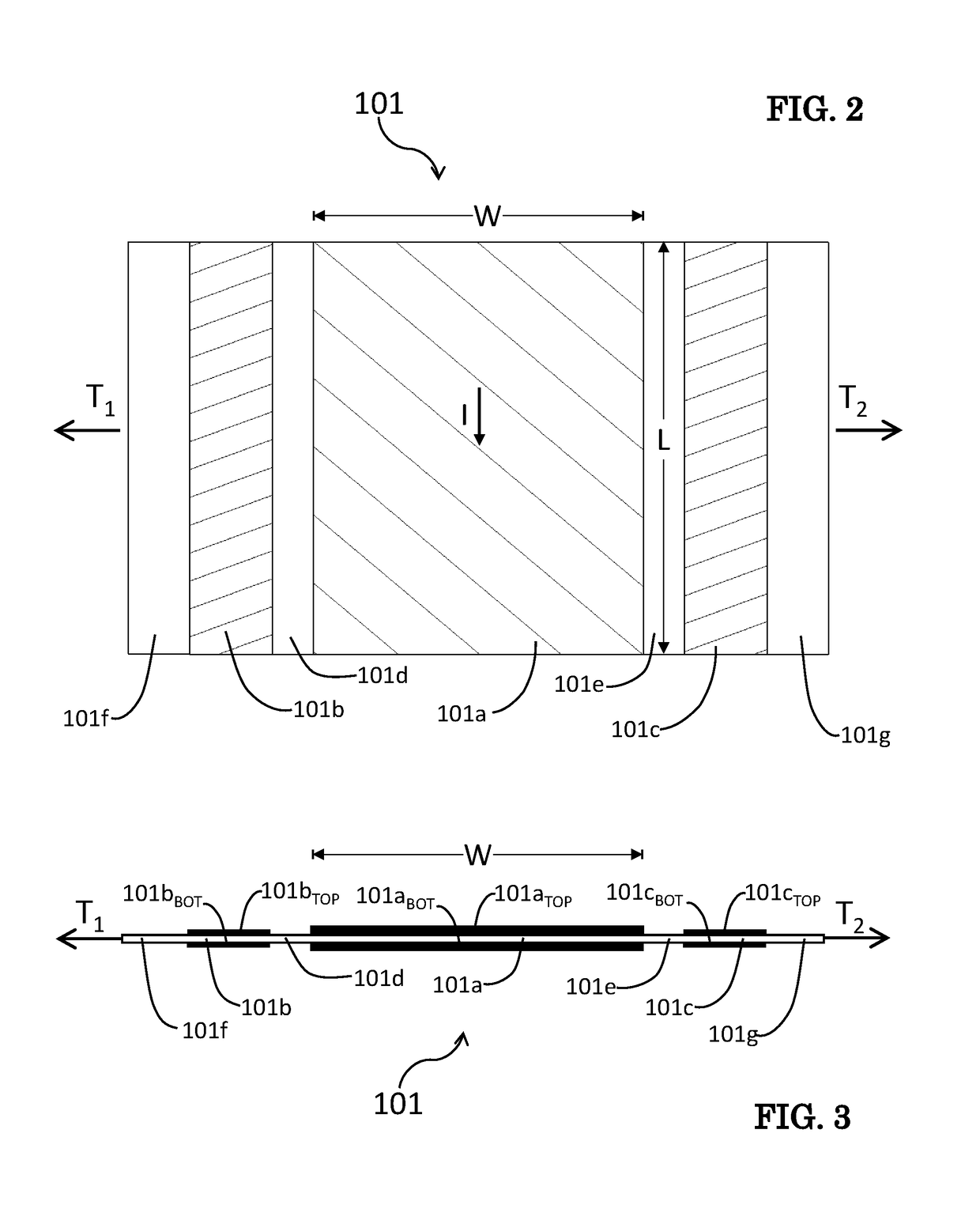
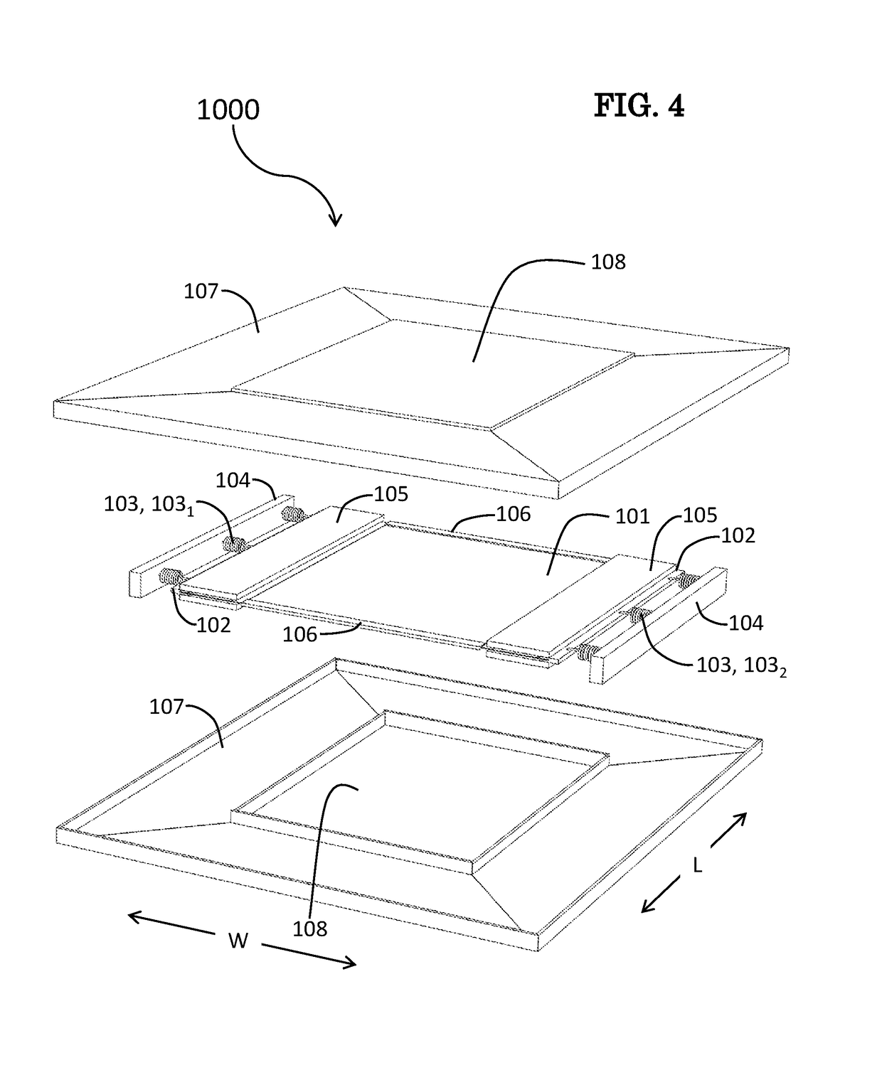
[0031]An example of inventive practice is now described with reference to FIG. 2, FIG. 3, FIG. 4 and FIG. 5. FIG. 2 and FIG. 3 show an inventive sensing sheet 101 with various areas identified. Area 101a is the current conducting area; areas 101b and 101c are the piezoelectric areas; areas 101f and 101g are the attachment areas; and areas 101d and 101e are the bonding areas. Area 101a represents the area...


PUM


Abstract

An exemplary magnetic flux sensor in accordance with the present invention is characterized by an electrical output that is proportional to the total static and dynamic flux passing normally through a large area. An oscillating electrical current passing down a conducting area produces Lorentz forces, which are transferred to piezoelectric areas. The piezoelectric areas produce electrical voltage at the oscillation frequency whereby amplitude is proportional to the total magnetic flux passing normally through the conducting area. Demodulating the voltage provides an electrical signal with high sensitivity, dynamic range, and noise immunity.

Description

STATEMENT OF GOVERNMENT INTEREST[0001]The invention described herein may be manufactured and used by or for the Government of the United States of America for governmental purposes without payment of any royalties thereon or therefor.BACKGROUND OF THE INVENTION[0002]The present invention relates to magnetic flux sensors, more particularly to magnetic flux sensors suitable for sensing magnetic flux through relatively large areas.[0003]There currently exists no practical method to measure the total static and dynamic magnetic flux passing normally through a large area. Semiconductor Hall devices are commonly used in magnetic machines, but they are small and essentially sample a single point. Magnetoresistive devices are becoming more practical; however, they are small and they sense flux down the device axis and not though the sensor thickness.[0004]Many devices would benefit from a large area magnetic flux sensor. For example, an electrodynamic actuator produces forces proportional t...

Claims


Application Information

Patent Timeline
Patent Type & Authority Patents(United States)
IPC IPC(8): G01R33/02G01R33/028
CPCG01R33/028G01R33/072
Inventor MIESNER, JOHN E.
Owner THE UNITED STATES OF AMERICA AS REPRESENTED BY THE SECRETARY OF THE NAVY
Why Eureka
Try Eureka