Surgical torque limiter

a torque limiter and torque technology, applied in the field of torque limiters, can solve the problems of limited torque, high cost, and high complexity of common torque wrenches, and influence the cleanability of surgical instruments

Inactive Publication Date: 2019-02-05
41MEDICAL AG
View PDF5 Cites 1 Cited by
  • Summary
  • Abstract
  • Description
  • Claims
  • Application Information

AI Technical Summary

Benefits of technology

[0010]It is the object of the invention to create a coupling device pertaining to the technical field initially mentioned, which allows the use of mono-block components, especially a mono-block handle and a mono-block shaft. A further objective of the present invention is to provide a coupling device allowing an easy switching of the pre-defined torque to at least two different torque levels.
[0012]By using the magnetic interaction of magnets located in pockets arranged along the longitudinal axis of the handle with the at least one protrusion, a very simple torque limiter is provided which essentially only includes two mono-block components which provide for a reliable cleaning and sterilization, especially since both the handle and the shaft may be easily disassembled prior to any cleaning or sterilization step. Further, by varying the interaction of the at least one protrusion with either said first or said second pocket, it is possible to adjust the torque level of the torque limiter by inserting the shaft turned by 180° into the handle. Hence, a very simple adjustment of the torque level is made possible.
[0028]Having two protrusions allows to increase the torque level of the inventive torque limiter, as the at least one magnet of both said first pocket and said second pocket will exert a magnetic force onto said two protrusions.
[0029]The first protrusion and the second protrusion are preferably of different lengths. This allows providing for different torque levels depending on the direction the shaft is arranged in the handle. For example, in the case where the first protrusion is longer as the second protrusion and the shaft is arranged in the handle in a first orientation, where said first protrusion is arranged in said first pocket, said first protrusion may interact with the at least one magnet arranged in said first pocket. However, when the shaft is arranged in said handle in a second orientation where the second, shorter protrusion is arranged in said first pocket, the second protrusion does not span a sufficient length of said pocket to interact with the at least one magnet in said pocket. Hence, no magnetic force will be exerted by the at least one magnet in said first pocket onto said second protrusion. Therefore, the resulting total magnetic force exerted onto said two protrusions varies depending on the orientation said shaft is arranged in said handle, thus allowing to vary the torque level to two different values with a single handle and shaft.
[0033]Hence, depending on the pocket the at least one protrusion is arranged in, a different force will be exerted thereon, following the law of the lever. This allows the generation of different torque levels even when using magnets having the same magnetization for both said first and said second pockets, as the force exerted onto said at least one protrusion increases with increasing distance of said at least one magnet from the axis of said through bore.

Problems solved by technology

Furthermore, often a limited torque is required such as to prevent damage to the drive in a screw or similar, such as to allow a subsequent removal of the screw or similar.
Common torque wrenches often are very complexly built, expensive and need regular calibration to guarantee the desired torque.
The complexity of the existing devices often influences the cleanability of these surgical instruments.
Furthermore, torque wrenches are expensive devices and most often only are designed to control one level of torque per wrench type.
One major drawback of the torque limiter arrangements known in the prior art is that they require different separate parts cooperating with each other, some of these parts even being movable in respect to other parts.
Especially in connection with surgical instruments, such as surgical screw drivers, assemblies of different parts and movable parts may not be easily cleaned and sterilized, especially since body fluids or tissue parts may remain stuck between assembled parts or jammed under a movable part.
However, insufficient cleaning and sterilization may be a serious threat to patients subsequently treated with said instruments.
Further, either the torque limiter according to the prior art only have a single pre-defined torque level or the switching to a different torque level requires time-consuming manual adjustment.

Method used


Image

  • Surgical torque limiter
  • Surgical torque limiter
  • Surgical torque limiter

Examples


second embodiment

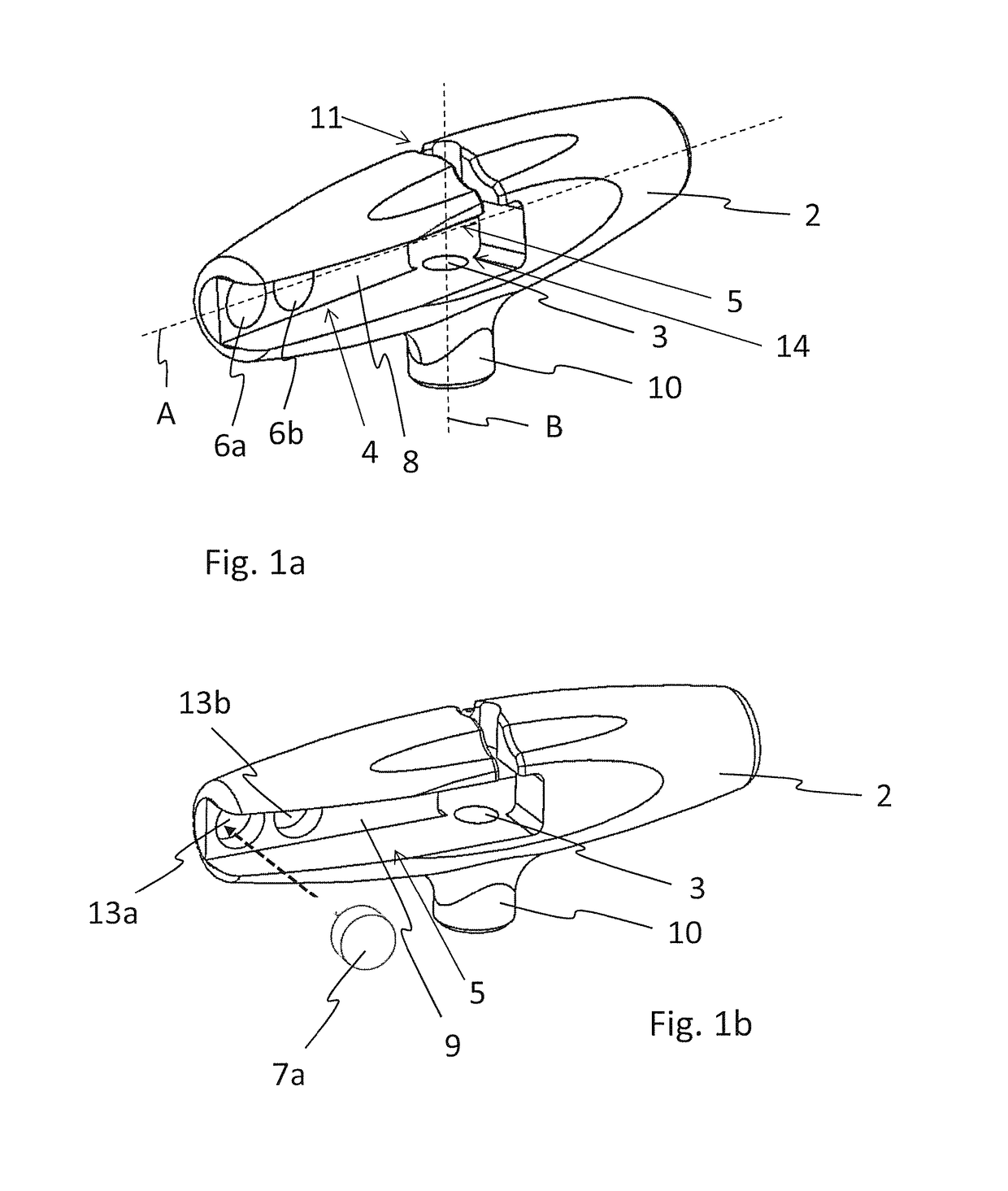
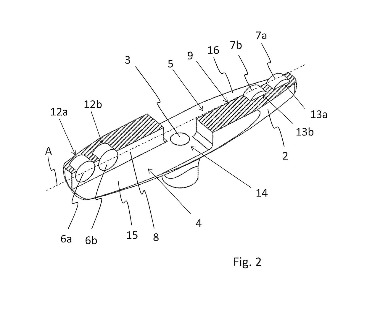
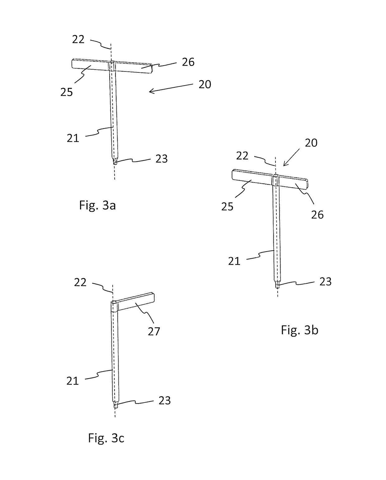
[0064]FIG. 6 shows a torque limiter 1. The protrusions 25, 26 of shaft 21 only interact with the second magnet 6b and the fourth magnet 7b, while the length of both protrusions 25, 26 is not sufficient to allow an interaction with the first magnet 6a or the third magnet 7a. The torque level of this embodiment equals the exerted force which is the sum of the force-distance pairs:

Exerted force=((Magnetization second magnet 6b×D2)+(Magnetization third magnet 7b×D3))

[0065]With this system a torque limiter kit can comprise one single handle 2 with multiple shafts 20, each shaft 20 yielding an individual torque level when arranged in said handle 2.

third embodiment

[0066]Referring to FIGS. 7a to 7c, a torque limiter 1 according to the present invention is shown. The first protrusion 25 of the shaft 20 has a greater length than the second protrusion 26. Further, the first magnet 6a and the second magnet 6b are arranged at different distances D5, D6 compared to the distances D1, D2 according to the embodiment as shown in FIGS. 5a and 5b.

[0067]The force exerted by the magnets 6a, 6b, 7a, 7b onto said two protrusions 25, 26 is based on the multiplication of the magnetization of each magnet 6a, 6b, 7a, 7b and the distance between the corresponding magnet 6a, 6b, 7a, 7b and the axis B of the central through bore 3. FIG. 7a shows the arrangement of the shaft 20 in handle 2 in a first orientation, where the first protrusion 25 is arranged in the first pocket 4 and the second protrusion 26 is arranged in the second pocket 5. The exerted force is given by:

Exerted force=((Magnetization first magnet 6a×D5)+(Magnetization second magnet 6b×D6)+(Magnetizati...


PUM


Abstract

The present application relates to a torque limiter (1) comprising a handle (2) with a mono-block cylindrical handle-body. The cylindrical handle-body includes a central through bore (3) having an axis (B) at a right angle to a longitudinal axis (A) of the cylindrical handle-body as well as a first pocket (4) and a second pocket (5). The first pocket (4) is arranged on a first side and the second pocket (5) is arranged on a second side of said cylindrical handle-body opposite of said first side. The first pocket (4) and the second pocket (5) are arranged along said longitudinal axis (A) and intersect each other in the area of said central through bore (3), each of said first pocket (4) and said second pocket (5) comprising at least one magnet (6a, 6b, 7a, 7b; 35). Further, the torque limiter (1) comprises a mono-block shaft (20) having a central shaft (21) removably arranged in said central through bore (3), said central shaft (21) having a drive (23) arranged at a first end. The central shaft (21) comprises at least one protrusion (25, 26; 27) arranged at a second end and being at a right angle to a central axis (22) of said central shaft (21), said at least one protrusion (25, 26; 27) being sized and shaped to be arranged within said first pocket (4) or said second pocket (5) and to magnetically interact with the at least one magnet (6a, 6b, 7a, 7b; 35) arranged in said first pocket (4) or said second pocket (5).

Description

TECHNICAL FIELD[0001]The invention relates to a torque limiter for a surgical device.BACKGROUND ART[0002]Bone screws are implantable medical fixation devices used in many fields of surgery, like traumatology, spine surgery and dental surgery. For different reasons, the insertion torque is an important factor for success of the treatment. In spinal surgery for example, a maximal insertion torque is defined to prevent bone from cracking. In traumatology another reason for screw insertion with a controlled torque is the prevention of cold-welding between plates and screws, which renders implant removal impossible.[0003]In dental applications, a too high torque indicates a not correctly prepared bone bed, which might influence osseo-integration of an implant. Furthermore, often a limited torque is required such as to prevent damage to the drive in a screw or similar, such as to allow a subsequent removal of the screw or similar.[0004]The insertion torque usually needs to be controlled t...

Claims


Application Information

Patent Timeline
Patent Type & Authority Patents(United States)
IPC IPC(8): A61B17/88B25B23/142A61B17/00A61B90/00
CPCB25B23/1427A61B17/8875A61B2090/031A61B2017/0046
Inventor OVERES, TOMFRIGG, ROBERT
Owner 41MEDICAL AG
Why Eureka
Try Eureka