Systems and methods for actuating a transformer neutral blocking system

a transformer and neutral blocking technology, applied in the direction of electrical equipment, arrangements responsive to excess current, and arrangements responsive to excess voltage, can solve the problems of excessive reactive power loss, damage and the potential damage of electrical equipment connected to that power source, and achieve the effect of decoupling the required power components, heating, and/or failure of such transformers

Active Publication Date: 2019-02-05
TECHHOLD LLC
View PDF5 Cites 13 Cited by
  • Summary
  • Abstract
  • Description
  • Claims
  • Application Information

AI Technical Summary

Problems solved by technology

Harmonics and quasi-DC currents can cause the input voltage and current (and resulting power) of a power signal to vary dramatically, causing a potential for damage to electrical equipment connected to that power source.
These DC currents can cause half-cycle saturation in power transformer cores which in turn can result in excessive reactive power losses, heating, damage and / or failure of such transformers.
This harmonic content in turn can cause power system relays to trigger, which can decouple required power components.
This in turn can result in the collapse of local or wide area portions of a power grid.
These solutions can allow for unintentionally open grounding connections to the transformer neutral, or require expensive electronics for handling ground fault conditions.
These solutions typically require expensive power electronics, and are constantly active, such that any failure would render these systems unreliable.
A third class of solutions generally uses a resistive approach in which fixed value resistors are used to continuously reduce the DC current in the neutral to ground connection of a transformer; however in these approaches, the resistors typically must have a high resistance value and would only reduce, not eliminate the DC or quasi-DC neutral current.
As such, there exists no solution that provides a reliable, low cost protection circuit compatible with current power delivery systems.

Method used


Image

  • Systems and methods for actuating a transformer neutral blocking system
  • Systems and methods for actuating a transformer neutral blocking system
  • Systems and methods for actuating a transformer neutral blocking system

Examples


Embodiment Construction

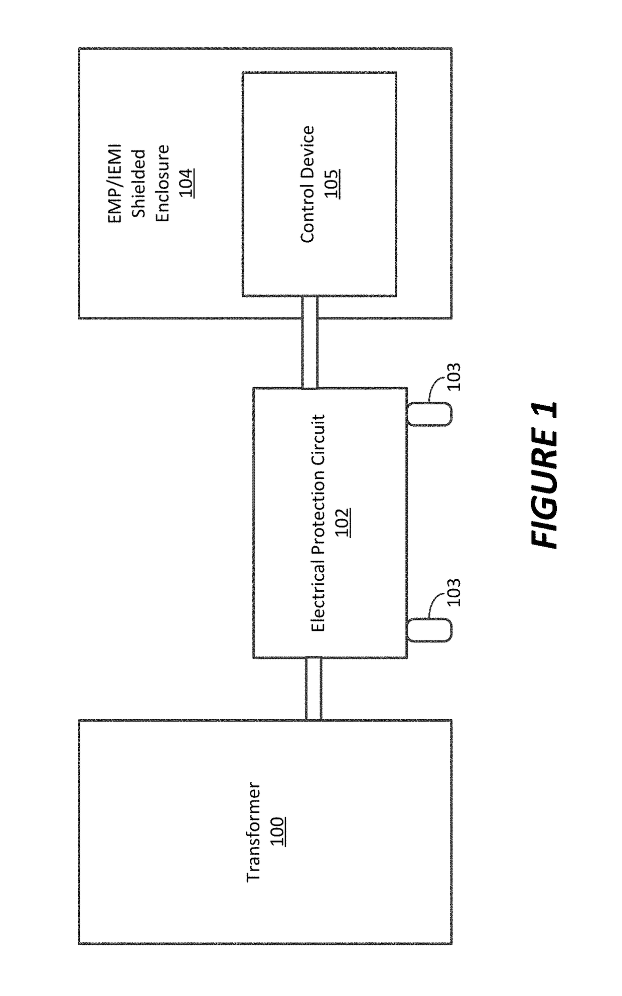
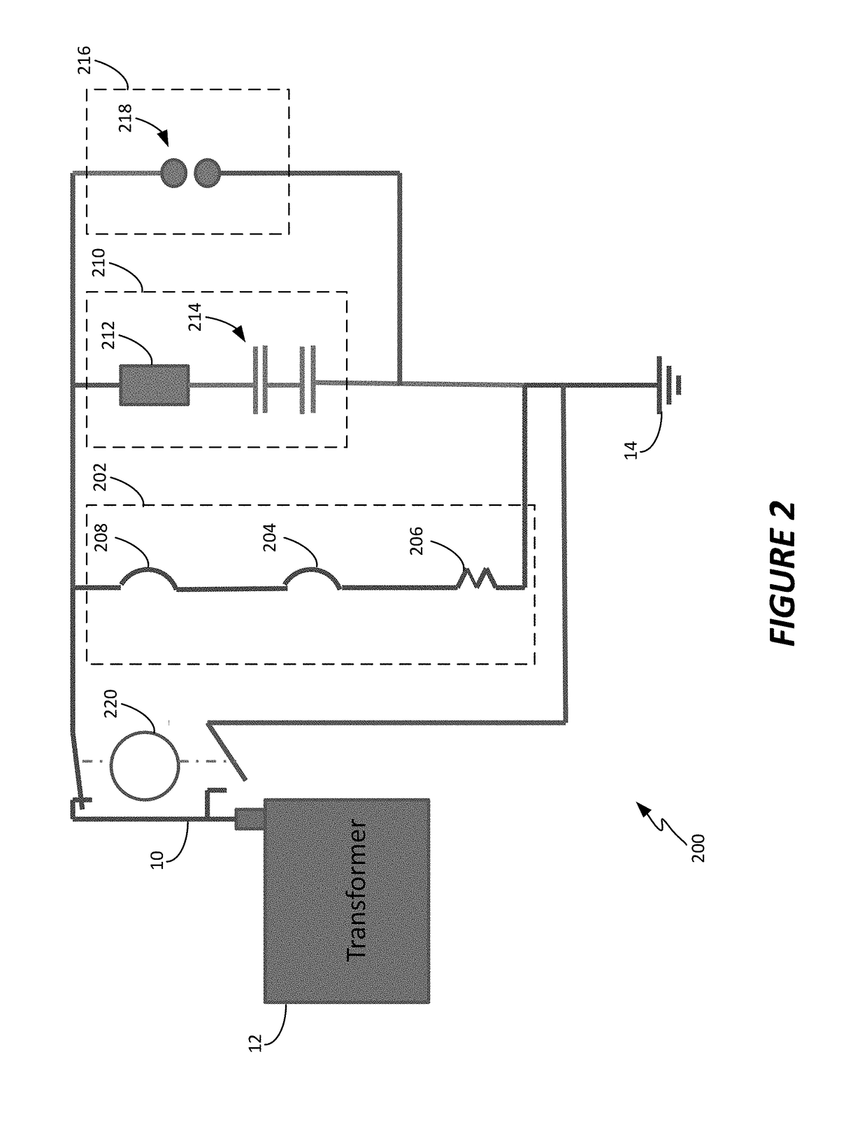
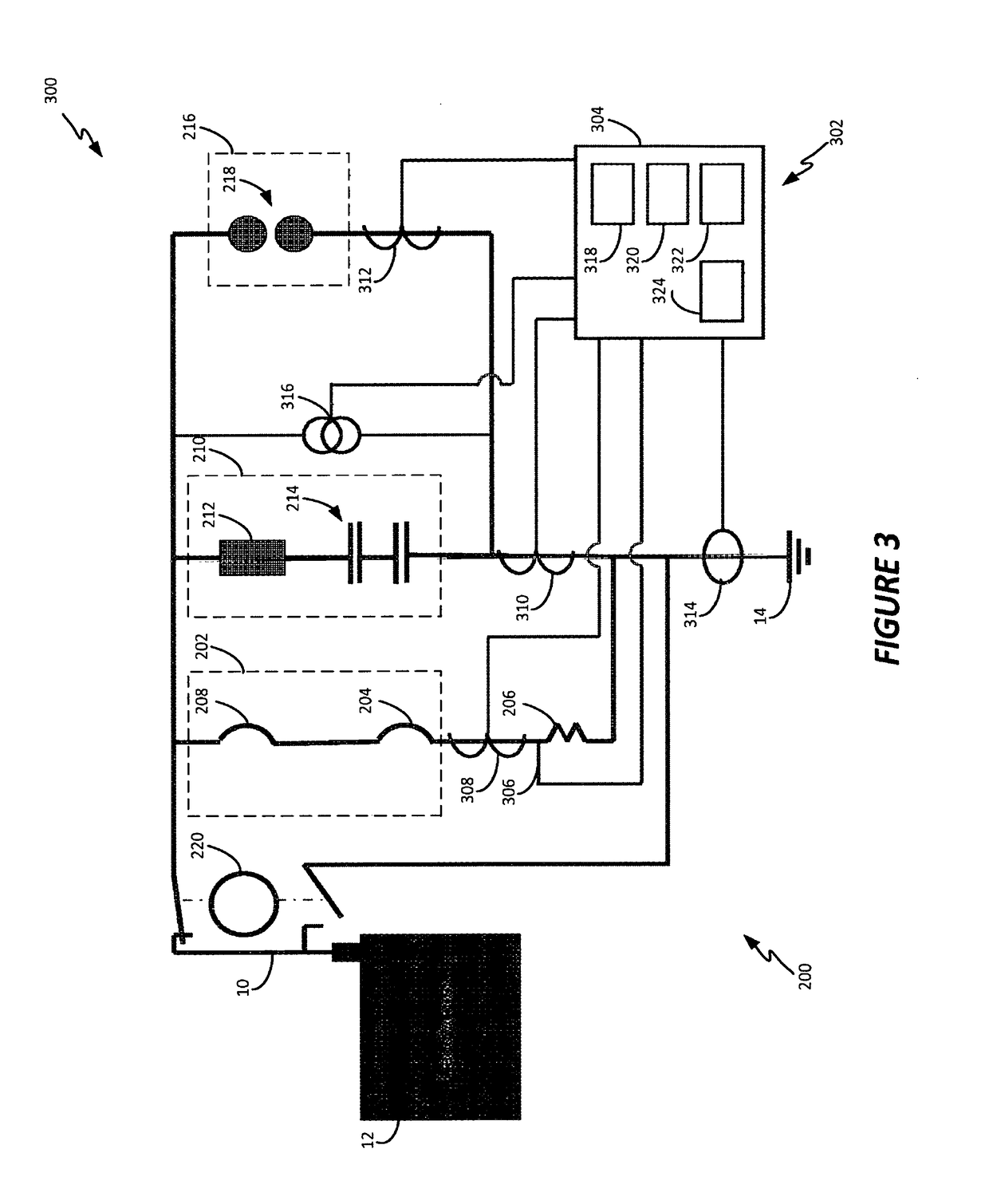
[0029]In general, the present disclosure describes systems and methods for protecting power utility transformers and other electrical or electro-mechanical equipment from damaging quasi-DC currents and as a result harmonic content on a power line. Large quasi-DC neutral currents as well as powerline harmonic currents are the result of geomagnetic disturbances (GMD) such as geomagnetic (solar) storms, high altitude electromagnetic E3 pulse (HEMP-E3) or other electrical equipment, such as switching power supplies, arc welding equipment, plasma cutting equipment, electric discharge machining equipment, arc lamps, etc., which are on the same power grid or local power circuit. Overall, the present disclosure describes methods and systems for sensing the harmonic content of a 50 Hz or 60 Hz power line source, and / or potentially damaging neutral quasi-DC currents, to allow critical electrical equipment to be switched to a protective mode of operation in case such harmonics or quasi-DC curr...


PUM


Abstract

A control device for an electrical protection circuit for use in an alternating current system including a transformer is disclosed. An example system includes a first measurement probe, a second measurement probe configured to measure an electrical property within the electrical protection circuit, and a control module, including a processing device. The control module is configured to monitor a measurement from the first measurement probe and transmit a protection activation control signal to the switch assembly based on the measurement from the first measurement probe exceeding a first predetermined threshold. The control module is also configured to monitor a measurement from the second measurement probe and transmit a protection deactivation control signal to the switch assembly based on the measurement from the second measurement probe satisfying a second predetermined threshold.

Description

CROSS REFERENCE TO RELATED APPLICATION[0001]The present application claims priority to U.S. Ser. No. 62 / 100,395, titled SYSTEMS AND METHODS FOR ACTUATING A TRANSFORMER[0002]NEUTRAL BLOCKING CIRCUIT, filed on Jan. 6, 2015, the disclosure of which is hereby incorporated by reference in its entirety.TECHNICAL FIELD[0003]The present application relates generally to systems and methods for actuating a transformer neutral blocking circuit.BACKGROUND[0004]Electrical equipment, and in particular electrical equipment operating using alternating current, is subject to varying input signals and conditions. In typical arrangements, alternating current devices in the United States expect to receive a 60 Hz power line source (or 50 Hz in Europe) having a predetermined magnitude (e.g., 120 Volts). Although these power sources may vary somewhat, devices made for use with a particular current can typically handle some slight variation in the power signal received.[0005]In some cases, a power signal ...

Claims


Application Information

Patent Timeline
Patent Type & Authority Patents(United States)
IPC IPC(8): H02H7/04H02H3/08H02H3/20H02H5/00H02H3/50
CPCH02H7/04H02H3/08H02H5/005H02H3/50H02H3/20
Inventor FUCHS, GREGJENSEN, WALLACEFAXVOG, FREDERICK R.JACKSON, DAVID BLAKENORDLING, GALE K.
Owner TECHHOLD LLC
Why Eureka
Try Eureka