Polarizing plate, method of manufacturing the same, and optical apparatus
a technology of polarizing plate and manufacturing method, which is applied in the direction of polarizing elements, instruments, optics, etc., can solve the problems of narrow grid width, difficult to maintain reliability as a polarizing plate, and difficulty in actually forming a pattern where the grid width is narrowed, and achieve excellent controllability of reflectance characteristics and transmittance characteristics. high
- Summary
- Abstract
- Description
- Claims
- Application Information
AI Technical Summary
Benefits of technology
Problems solved by technology
Method used
Image

Examples
example 2
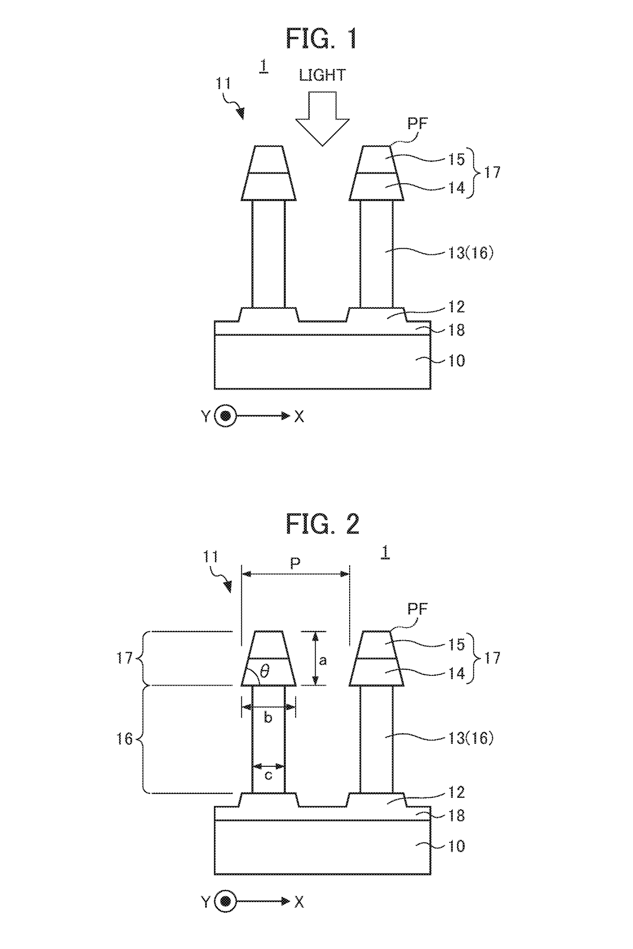
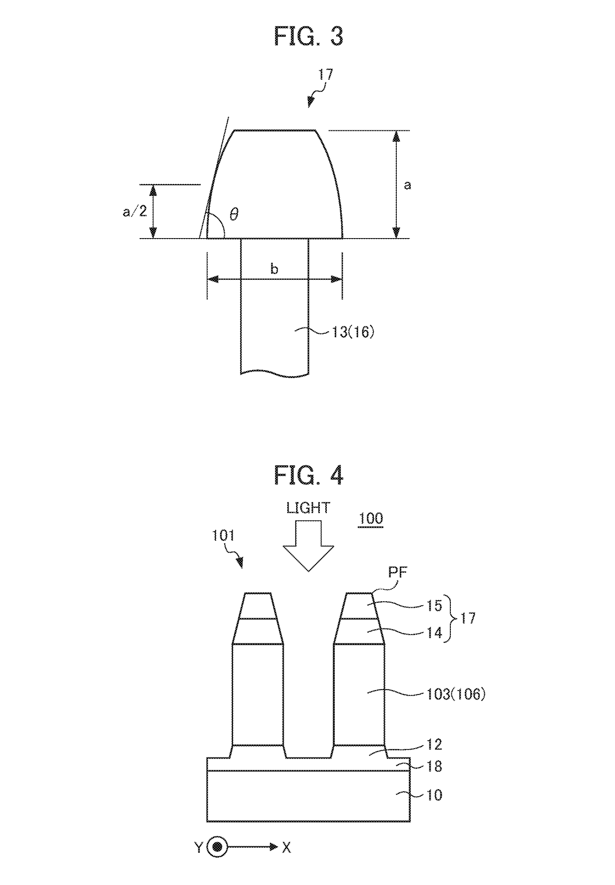
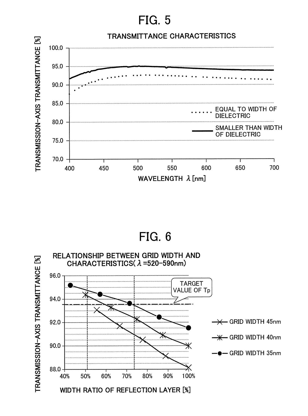
[0104]In Example 2, the polarizing plate 1 having the structure illustrated in FIG. 1, of which the grid width was changed to 35 nm, 40 nm, 45 nm, 50 nm, and 55 nm and of which the ratio of the width of the reflection layer to the grid width was changed was used for simulation. More specifically, simulation was performed for light in the green band (wavelength λ=520 to 590 nm) of incident light.
[0105]FIG. 6 is a graph illustrating results of simulation verification of the relationship between the width of the reflection layer of the polarizing plate 1 having the structure illustrated in FIG. 1 and the transmission-axis transmittance Tp. More specifically, FIG. 6 illustrates the relationship between the ratio of the width of the reflection layer to the grid width and the transmission-axis transmittance Tp. The horizontal axis represents the width ratio (%) of the reflection layer, and the vertical axis represents the transmission-axis transmittance Tp (%). In addition, FIG. 7 is a gr...
example 3
[0117]FIG. 10 is a schematic cross-sectional view illustrating a polarizing plate 300 having a rectangular grid tip 17B. In FIG. 10, the components common to the polarizing plate 1 illustrated in FIG. 1 are denoted by the same reference numerals. This polarizing plate 300 has the same configuration as that of the polarizing plate 1 illustrated in FIG. 1, except that the grid tip 307 is configured with a dielectric layer 304 and an absorption layer 305, each of which has not a tapered shape but a rectangular shape. The polarizing plate 300 corresponds to the polarizing plate 1 illustrated in FIG. 1 where the inclination angle θ of the side face of the grid tip of the polarizing plate 1 is 90°. In this example, with respect to the polarizing plate 1 having the structure illustrated in FIG. 1, simulation of changing the inclination angle θ and variously changing the ratio of the height a of the grid tip to the grid width b was performed. In addition, in this example, simulation of the ...
example 4
[0128]Next, the polarizing plate having the wire grid structure illustrated in FIG. 1 was actually manufactured, and the obtained optical characteristics were compared with simulation results. FIG. 21 is a graph illustrating comparison and verification results of actual measurement values and simulation results of the transmission-axis transmittance Tp with respect to the inclination angle θ of the side face of the grid tip in a case where the ratio of the height a of the grid tip to the grid width b is 8:9.
[0129]In FIG. 21, blank points are the same as the simulation results illustrated in FIG. 15. Meanwhile, with respect to the cases where the average values of the inclination angle θ are 77° and 74°, the actual measurement values are indicated by the black points. Herein, in a case where the average value of the inclination angle θ is 74°, the actual measurement value of the blue band (wavelength λ=430 to 510 nm) and the actual measurement value of the green band (wavelength λ=52...
PUM
 Abstract
Description
Claims
Application Information
 - R&D
- Intellectual Property
- Life Sciences
- Materials
- Tech Scout
- Unparalleled Data Quality
- Higher Quality Content
- 60% Fewer Hallucinations
Browse by: Latest US Patents, China's latest patents, Technical Efficacy Thesaurus, Application Domain, Technology Topic, Popular Technical Reports.
© 2025 PatSnap. All rights reserved.Legal|Privacy policy|Modern Slavery Act Transparency Statement|Sitemap|About US| Contact US: help@patsnap.com