Turbine minidisk bumper for gas turbine engine

a gas turbine engine and mini-disk technology, applied in the direction of machines/engines, sustainable transportation, mechanical equipment, etc., can solve the problem of significantly more expensive service of the turbine section

Active Publication Date: 2019-03-05
RTX CORP
View PDF22 Cites 2 Cited by
  • Summary
  • Abstract
  • Description
  • Claims
  • Application Information

AI Technical Summary

Benefits of technology

[0011]In a further embodiment of any of the above, the hub includes circumferentially spaced radially outwardly extending first tabs. The axial extension includes circumferentially spaced radially inwardly extending second tabs. The first and second tabs are axially aligned with one another and fingers of the sleeve are received in circumferential gaps provided between the first and second tabs to prevent relative circumferential movement between the first and second tabs.

Problems solved by technology

One prior art arrangement required the entire bearing and seal assembly to be removed to gain access to the annular recess, which made servicing the turbine section considerably more costly.

Method used


Image

  • Turbine minidisk bumper for gas turbine engine
  • Turbine minidisk bumper for gas turbine engine
  • Turbine minidisk bumper for gas turbine engine

Examples


Embodiment Construction

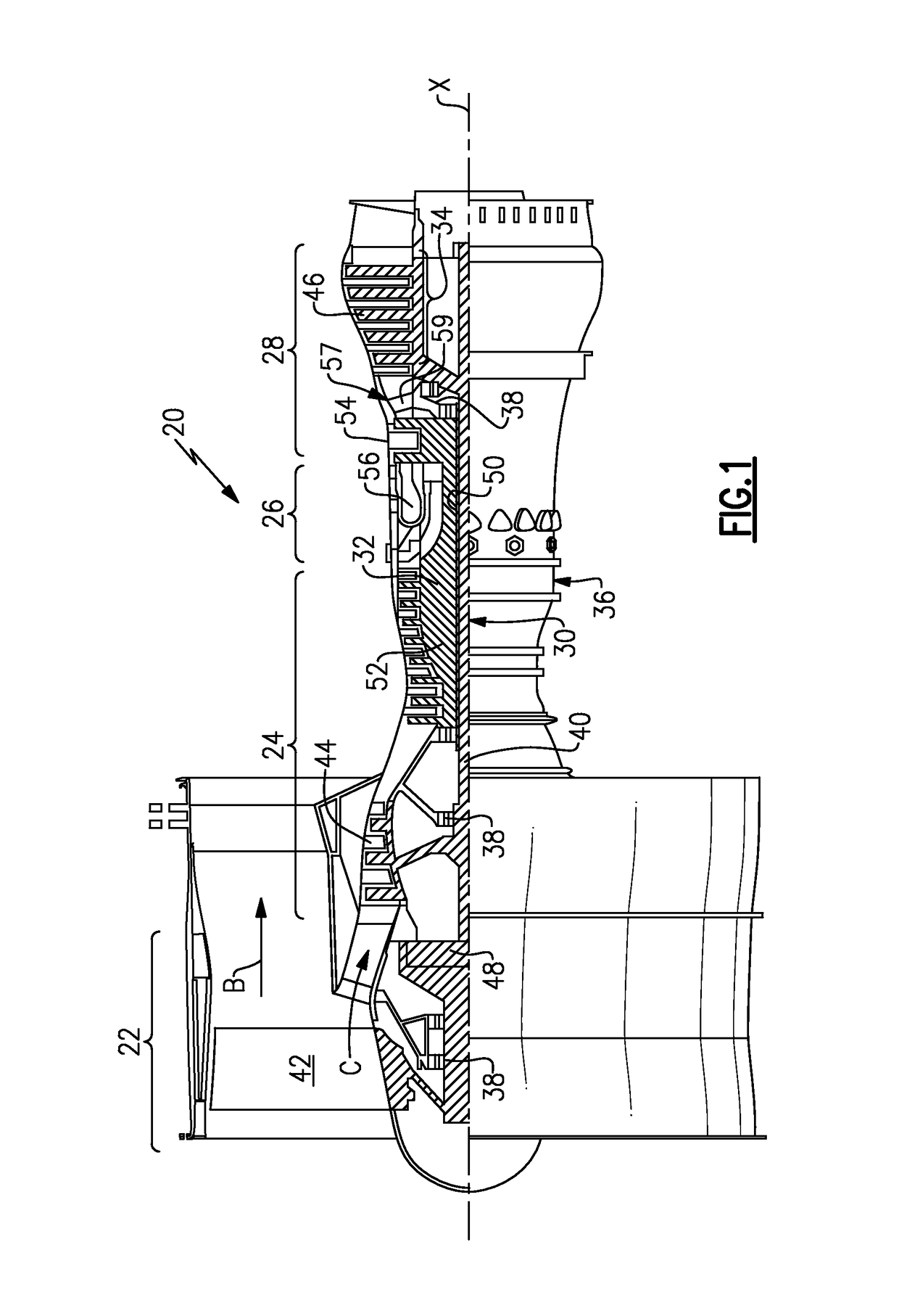
[0033]FIG. 1 schematically illustrates an example gas turbine engine 20 that includes a fan section 22, a compressor section 24, a combustor section 26 and a turbine section 28. Alternative engines might include an augmenter section (not shown) among other systems or features. The fan section 22 drives air along a bypass flow path B while the compressor section 24 draws air in along a core flow path C where air is compressed and communicated to a combustor section 26. In the combustor section 26, air is mixed with fuel and ignited to generate a high pressure exhaust gas stream that expands through the turbine section 28 where energy is extracted and utilized to drive the fan section 22 and the compressor section 24.

[0034]Although the disclosed non-limiting embodiment depicts a turbofan gas turbine engine, it should be understood that the concepts described herein are not limited to use with turbofans as the teachings may be applied to other types of turbine engines and other turbo m...


PUM


Abstract

An assembly for a gas turbine engine includes a minidisk that includes an axial extension extending from a disc. The axial extension includes an inner diameter surface and a recess arranged radially opposite the inner diameter surface. The recess provides a radially outwardly extending flange and a bumper extending radially inward from and proud of the inner diameter surface. A method of working on a gas turbine engine section includes inserting a tool into a cavity beneath a seal assembly, and engaging a flange of a minidisk with the tool to manipulate first and second rotors with respect to one another.

Description

TECHNICAL FIELD[0001]This disclosure relates to a minidisk for a gas turbine engine turbine section, and more particularly, the disclosure relates to a feature on the minidisk for assembly and disassembly of the turbine section.BACKGROUND OF THE INVENTION[0002]Gas turbine engines typically include a compressor section, a combustor section and a turbine section. During operation, air is pressurized in the compressor section and is mixed with fuel and burned in the combustor section to generate hot combustion gases. The hot combustion gases are communicated through the turbine section, which extracts energy from the hot combustion gases to power the compressor section and other gas turbine engine loads.[0003]Early minidisks were used as windage covers disposed upon rotating gas turbine engine rotors. More modern minidisks are also used to cool the turbine rotor. An axial extension of the minidisk may extend into an area having a seal assembly and bearing.[0004]A typical turbine sectio...

Claims


Application Information

Patent Timeline
Patent Type & Authority Patents(United States)
IPC IPC(8): F02C3/04F01D5/06F01D5/02
CPCF02C3/04F01D5/02F01D5/066F01D5/026Y02T50/671F05D2230/70Y02T50/60
Inventor SANDOVAL, JONATHAN PERRY
Owner RTX CORP
Why Eureka
Try Eureka