Impact beam and method for producing an impact beam

a technology of impact beams and beams, which is applied in the direction of doors, transportation and packaging, vehicle sub-unit features, etc., can solve the problems of excessive weight of components, and achieve the effect of high degree of freedom in construction, weight optimization, and cost-effectiveness

Active Publication Date: 2019-03-26
BENTELER AUTOMOBILTECHNIK GMBH
View PDF7 Cites 1 Cited by
  • Summary
  • Abstract
  • Description
  • Claims
  • Application Information

AI Technical Summary

Benefits of technology

[0017]So that conventional extrusion tools with an extrusion width of up to ca. 100 cm may be used cost-efficiently the extrusion profile, also called the light metal profile, is initially produced with an extrusion width. To this end, an uneven extrusion cross section is produced. In particular, the extrusion cross section is configured as a wave-shaped profile.
[0027]In the case of a cross member, the terminal portion is preferably configured in two parts. On an outer end of the terminal portion, the wall thickness is configured to be smaller. On a part of the terminal portion oriented toward the central portion, also called the connecting portion, in contrast a larger wall thickness is formed. In this case a connecting region of the cross member is provided on crash boxes and / or longitudinal members. By the larger wall thickness more stability is provided here for mounting the cross member and in the event of a crash the cross member is prevented by the larger wall thickness from being pulled off the crash boxes. A reduced wall thickness is provided in turn toward the outer end of the terminal portion.
[0029]Moreover, particularly preferably the outer terminal edges of the impact beam, in particular in a door impact beam, extend at an angle not equal to 90° relative to the longitudinal axis. Preferably the angle is configured to be between 60° and 88°, in particular between 70° and 85°. By this measure it is possible to achieve a component length of the impact beam, in particular the door impact beam, wherein the component length is greater than the extrusion width and, in particular, greater than the working width. It is thus possible to produce a component with a component length, wherein the extrusion width is markedly smaller and / or the working width is smaller relative thereto. Micro-crack formation in the material joints, produced during the flattening and / or widening, may be reduced since only a smaller degree of flattening and / or widening is required in order to produce a component of sufficient component length.
[0038]An alternative, particularly preferred variant provides that the extrusion profile is trimmed and / or cut to length at an angle of 90°, in particular at an angle of less than 90° to the extrusion direction. Thus it is possible to achieve a component length which is greater than the working width.

Problems solved by technology

However, it is non-visible component, resulting in the requirements also being set that it is produced as cost-effectively as possible and at the same time has a low dead weight.
A drawback with the aforementioned production method, however, is that the components are generally only produced with a uniform wall thickness and thus in order to achieve the required load-bearing capacity, in particular crash performance, they have a component weight which is consequently too high.

Method used


Image

  • Impact beam and method for producing an impact beam
  • Impact beam and method for producing an impact beam
  • Impact beam and method for producing an impact beam

Examples


Embodiment Construction

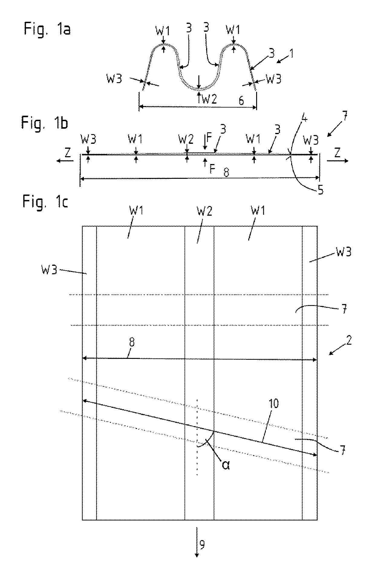
[0044]FIGS. 1a to c show a method according to the invention for producing an extruded profile 1 by flattening and / or widening and separating and / or trimming the semi-finished products 7 produced thereby. According to FIG. 1a, an extruded profile 1 is produced with a wave-shaped and thus uneven cross section. In this case a centrally arranged wall thickness W2 which is larger than an external wall thickness W3 is present as well as a transition therebetween with the variable wall thickness W1 reducing from the wall thickness W2 to the wall thickness W3. The continuous thickness transition from the wall thickness W1 to the wall thickness W3 is thus easily able to be produced due to the extrusion. The change in wall thickness may be formed on only one side, for example the upper face 4, but also on the lower face 5 or on the upper face 4 and on the lower face 5 at the same time. This extruded profile 1 in turn has an extrusion width 6.

[0045]A flattening and / or widening is carried out ...


PUM

PropertyMeasurementUnit
angleaaaaaaaaaa
angleaaaaaaaaaa
angleaaaaaaaaaa

Abstract

An impact beam and a method of producing the impact beam for a motor vehicle is disclosed. A light metal profile with an extrusion width is produced by flattening the light metal profile to a working width and cutting to length to form semi-finished products. The semi-finished products are subjected to further treatment by press-forming techniques to form the impact beam. The impact beam has a longitudinal length which extends transversely to the direction of extrusion of the light metal profile.

Description

RELATED APPLICATIONS[0001]The present application claims priority from German Patent Application Number 10 2016 101 150.9 filed Jan. 22, 2016, the disclosure of which is hereby incorporated by reference herein in its entirety.FIELD OF THE INVENTION[0002]The present invention relates to an impact beam according to the preamble of Claim 1.[0003]The present invention further relates to a method for producing an impact beam according to the features in the preamble of Claim 11.BACKGROUND OF THE INVENTION[0004]From the prior art it is known to fit impact beams in motor vehicles in the region of points on the bodywork which are at risk of impact. These impact beams serve to conduct the force produced in the event of an impact in a targeted manner into a force path in order to keep the passenger compartment stable, therefore, and thus to protect the passengers. An impact beam is designed to be as rigid as possible. However, it is non-visible component, resulting in the requirements also be...

Claims


Application Information

Patent Timeline
Patent Type & Authority Patents(United States)
IPC IPC(8): B60J5/00B62D29/00B60R19/34B60R19/18B60J5/04B60R19/02
CPCB60J5/0444B60R19/18B62D29/008B60R19/34B60Y2410/12B60R2019/182B23P15/00
Inventor CLAUSEN, EDVIN LISTHITZ, ANDREASKAVIK, TOBIAS SVANTESSONBASTANI, AMIN FARJAD
Owner BENTELER AUTOMOBILTECHNIK GMBH
Why Eureka
Try Eureka